![Nissan Note — проверка системы и компонентов: руководство по диагностике [57/60]](/img/pdf.png)
Nissan Note — проверка системы и компонентов: руководство по диагностике [57/60]
![Nissan Note [57/60] Yoke check](/views2/1789832/page57/bg39.png)
STARTING SYSTEM
SC-57
C
D
E
F
G
H
I
J
L
M
A
B
SC
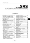
YOKE CHECK
Magnet is secured to yoke by bonding agent. Check magnet to see
that it is secured to yoke and for any cracks. Replace malfunctioning
partsasanassembly.
CAUTION:
Do not clamp yoke in a vice or strike it with a hammer.
ARMATURE CHECK
1. Continuity test (between two segments side by side).
● No continuity... Replace.
2. Insulation test (between each commutator bar and shaft).
● Continuity exists.... Replace.
3. Check commutator surface.
● Rough... Sand lightly with No. 500 - 600 emery paper.
SEL018Z
SEL019Z
SEL020Z
Содержание
- Contents p.1
- Starting charging system p.1
- Sectio p.1
- K electrical p.1
- Precautions for supplemental restraint system srs air bag and seat belt pre tensioner p.3
- Precautions p.3
- Special service tools p.4
- Preparation p.4
- Methods of preventing over discharge p.5
- How to handle battery p.5
- Checking electrolyte level p.5
- Battery p.5
- Sulphation p.6
- Specific gravity check p.6
- Battery p.6
- Battery test and charging chart p.7
- Battery p.7
- Chart i p.7
- Fig 1 discharging current load tester p.8
- Check battery type and determine the specified current using the following table p.8
- Chart ii p.8
- Battery p.8
- Battery p.9
- A slow charge p.9
- Set charging current to value specified in fig 2 if charger is not capable of producing specified current value set its charging current as close to that value as possible p.10
- Keep battery away from open flame while it is being charged p.10
- If battery temperature rises above 60 c 140 f stop charging always charge battery when its temperature is below 60 c 140 f p.10
- Fig 3 additional charge slow charge p.10
- Fig 2 initial charging current setting slow charge p.10
- Check battery type and determine the specified current using the table shown above p.10
- Caution p.10
- Battery p.10
- After starting charging adjustment of charging current is not necessary p.10
- When connecting charger connect leads first then turn on charger do not turn on charger first as this may cause a spark p.10
- Fig 4 initial charging current setting standard charge p.11
- Battery p.11
- B standard charge p.11
- Fig 5 additional charge standard charge p.12
- C quick charge p.12
- Battery p.12
- Set initial charging current to value specified in fig 6 if charger is not capable of producing spec ified current value set its charging current as close to that value as possible p.13
- Keep battery away from open flame while it is being charged p.13
- Fig 6 initial charging current setting and charging time quick charge p.13
- Do not use quick charge method on a battery whose specific gravity is less than 1 00 p.13
- Check battery type and determine the specified current using the table shown above p.13
- Caution p.13
- Be careful of a rise in battery temperature because a large current flow is required during quick charge operation if battery temperature rises above 60 c 140 f stop charging always charge battery when its temperature is below 60 c 140 f p.13
- Battery p.13
- After starting charging adjustment of charging current is not necessary p.13
- When connecting charger connect leads first then turn on charger do not turn on charger first as this may cause a spark p.13
- Removal and installation p.14
- Removal p.14
- Installation p.14
- Battery p.14
- System description k9k engine models p.15
- System description hr engine models p.15
- System description cr engine models p.15
- Charging system p.15
- Wiring diagram charge hr engine models p.17
- Charging system p.17
- Charging system p.19
- Inspection flow by charge warning lamp p.20
- Diagnosis procedure p.20
- Diagnosis chart by symptom p.20
- Charging system p.20
- Trouble diagnoses cr engine models p.20
- Pre diagnosis inspection p.20
- Inspection procedure p.21
- Charging system p.21
- Charge warning lamp line inspection p.21
- Inspection of insufficient alternator power generation p.22
- Charging system p.22
- Inspection of excessive alternator power generation p.23
- Dark current inspection p.23
- Charging system p.23
- Operation procedure of current measurement probe for consult ii p.24
- Charging system p.24
- Inspection flow by charge warning lamp p.25
- Diagnosis procedure p.25
- Diagnosis chart by symptom p.25
- Charging system p.25
- Trouble diagnoses hr engine models p.25
- Pre diagnosis inspection p.25
- Inspection procedure p.26
- Charging system p.26
- Charge warning lamp line inspection p.26
- Voltage detection line and charge warning lamp inspection p.27
- Inspection procedure p.27
- Charging system p.27
- Inspection of insufficient alternator power generation p.28
- Charging system p.28
- Inspection of excessive alternator power generation p.29
- Charging system p.29
- Dark current inspection p.30
- Charging system p.30
- Operation procedure of current measurement probe for consult ii p.31
- Charging system p.31
- Trouble diagnoses k9k engine models p.32
- Pre diagnosis inspection p.32
- Inspection flow by charge warning lamp p.32
- Diagnosis procedure p.32
- Diagnosis chart by symptom p.32
- Charging system p.32
- Inspection procedure p.33
- Charging system p.33
- Charge warning lamp line inspection p.33
- Voltage detection line and charge warning lamp inspection p.34
- Inspection procedure p.34
- Charging system p.34
- Charging system p.35
- Inspection of insufficient alternator power generation p.36
- Inspection of excessive alternator power generation p.36
- Charging system p.36
- Dark current inspection p.37
- Charging system p.37
- Operation procedure of current measurement probe for consult ii p.38
- Charging system p.38
- Removal and installation cr engine models p.39
- Removal p.39
- Charging system p.39
- Removal and installation hr engine models p.40
- Removal p.40
- Installation p.40
- Charging system p.40
- Installation p.41
- Charging system p.41
- Installation p.42
- Disassembly p.42
- Charging system p.42
- Removal and installation k9k engine models p.42
- Removal p.42
- Rear cover p.42
- Stator check p.43
- Rotor check p.43
- Rear bearing p.43
- Inspection p.43
- Charging system p.43
- Brush check p.43
- Ring fitting in rear bearing p.44
- Rear cover installation p.44
- Charging system p.44
- Assembly p.44
- Starting system p.45
- M t models p.45
- A t models p.45
- System description p.45
- Starting system p.47
- Starting system p.49
- Starting system p.51
- Removal and installation hr engine models p.51
- Removal and installation cr engine models p.51
- Removal p.51
- Installation p.51
- Starting system p.52
- Removal and installation k9k engine models p.52
- Removal p.52
- Installation p.52
- Disassembly and assembly p.52
- Through bolt m0t84585 p.53
- Starting system p.53
- 4 7 n m 0 5 0 2 kg m 39 62 in lb p.53
- Starting system p.54
- Starting system p.55
- Pinion clutch check p.55
- Magnetic switch check p.55
- Inspection p.55
- Brush check brush p.55
- Starting system p.56
- Brush spring check p.56
- Brush holder p.56
- Yoke check p.57
- Starting system p.57
- Armature check p.57
- Starting system p.58
- Pinion protrusion length adjustment clearance p.58
- Assembly p.58
- Not in the specified value adjust by adjusting plate p.59
- Starting system p.59
- Starter p.60
- Service data and specifications sds p.60
- Battery p.60
- Alternator p.60
Похожие устройства
-
 Nissan Murano z50Руководство пользователя
 -
 Nissan Murano z50Руководство пользователя ч2
 -
 Nissan Z50 (2002-2008)Руководство по эксплуатации
 -
 Nissan NoteWIPER, WASHER _ HORN
 -
 Nissan NoteROAD WHEELS _ TYRES
 -
 Nissan NotePOWER SUPPLY, GROUND _ CIRCUIT ELEMENTS
 -
 Nissan NoteSUPPLEMENTAL RESTRAINT SYSTEM _SRS_
 -
 Nissan NoteMAINTENANCE
 -
 Nissan NoteMANUAL TRANSAXLE
 -
 Nissan NoteSTEERING CONTROL SYSTEM
 -
 Nissan NoteSEAT
 -
 Nissan NotePOWER STEERING SYSTEM
Узнайте, как правильно проверить и обслуживать систему и её компоненты. Следуйте инструкциям по проверке магнита, якоря и коллекторов для обеспечения надежной работы.