
Ridgid SF-2500 SuperFreeze Инструкция по эксплуатации онлайн
WARNING!
Read this Operator’s Manual
carefully before using this tool.
Failure to understand and fol-
low the contents of this manual
may result in extensive prop-
erty damage and/or serious
personal injury.
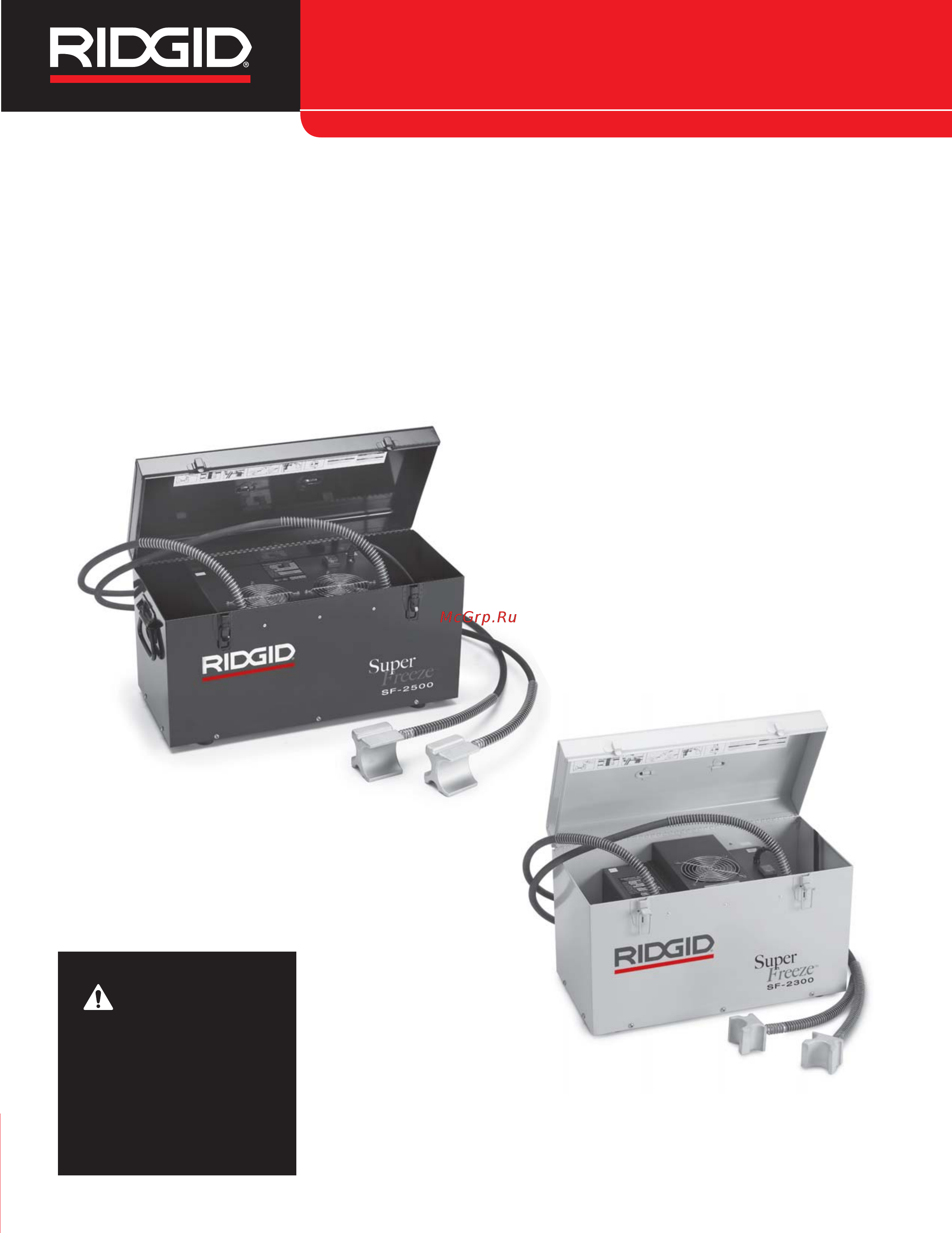
SF-2300/SF-2500
Manual
SuperFreeze
®
Pipe Freezing Units
• Français – 13
• Castellano – 27
•
Türkçe
– 41
• усский – 55
Содержание
- Manual 1
- Pipe freezing units 1
- Sf 2300 sf 250 1
- Superfreeze 1
- Pipe freezing units 2
- Sf 2300 2500superfreeze insidespr 2
- Superfreeze 2
- Table of contents 2
- Pipe freezing units 3
- Sf 2300 sf 2500 3
- Superfreeze 3
- Electrical safety 4
- General safety rules 4
- Personal safety 4
- Pipe freezing units 4
- Safety symbols 4
- Superfreeze 4
- Work area safety 4
- Description 5
- Description specifications and standard equipment 5
- Pipe freezing unit safety warnings 5
- Pipe freezing units 5
- Service 5
- Superfreez 5
- Tool use and care 5
- All superfreeze pipe freezing units come with the fol lowing two velcro straps with d ring quick grip clamp freeze gel water spray bottle operator s manual 6
- Parameter model sf 2500 115v sf 2500 230v sf 2300 230v 6
- Pipe freezing units 6
- Specifications 6
- Standard equipment 6
- Superfreeze 6
- The machine serial number is located on the control panel an additional decal is supplied that indicates the month and year of manufacture 05 month 13 year 6
- Machine and work area set up 7
- Pipe freezing units 7
- Pre operation inspection 7
- Superfreez 7
- 30 mm or larger plugs placed closer to a circu 8
- Apply freeze gel to the freeze head cavity if using end adapter or bushings apply freeze gel between the freeze head and the adapter and to the adapter sur face that contacts the pipe the freeze gel improves 8
- Capacities for copper tube and steel pipe 8
- Cavity req d bushing 8
- Choose the appropriate freeze head cavity for the size of pipe or tube to be frozen the capacities for copper tube and steel pipe are listed in the chart that follows adapter bushings are required in some appli cations if using on pipe or tube other than listed sizes the pipe tube diameter cannot be smaller than the freeze head bushing diameter 1 8 3 mm 8
- Determine if the piping is filled with water a plug cannot be frozen into partly filled pipes determine where the piping system needs to bro ken for the work that needs to be done locate piping system shut off valves or determine other methods to shut off system fluid flow to be used in case of emergency 8
- Determine location for freeze plug s the location must allow access for at least one freeze head if only a single plug is required it is preferred that there be enough space for both freeze heads freeze heads should not contact more than one pipe if the system will be soldered brazed welded or other heat adding processes performed the freeze plug s must be located as far away from the repair as possible excess heat can prematurely thaw the ice plug and allow water to flow while the system is open the freeze plugs should be a minimum of one foot 0 m away from the heat for each inch 25 mm of diameter for steel pipe or tube for all other materials the plug should be at least three feet 0 m away for each inch of pipe or tube diameter ice plugs must be more than one foot 0 m away from end caps elbows closed valves other ice plugs or similar obstructions placing an ice plug closer can cause splitting of the pipe or tube do not place ice plugs closer than 5 feet 1 m from a circulating hot wat 8
- Lating hot water main can prevent plug formation or can cause plug thawing 8
- Model freeze head copper tube cts steel pip 8
- Model freeze head copper tube dn steel pipe cavity end adapter 8
- Pipe freezing units 8
- Place the unit so that freeze heads can reach desired plug points locate superfreeze on a solid level sur face in an upright position if the unit is not upright and level it can cause damage to the compressor make sure the air inlet outlet to condenser are not blocked blocked condenser openings will slow or prevent the freezing process be sure to locate the pipe freezing unit away from where the repair will occur and not under the freeze heads this will help prevent the entry of water into the freezing unit and help prevent electrical shock 8
- Prepare the freeze plug locations remove all insula tion and coatings from the pipe down to bare metal if needed remove any corrosion with a wire brush coatings and corrosion insulate the pipe and can slow or prevent the freezing process 8
- Superfreeze 8
- Uncoil the hoses to the freeze heads use care not to twist or kink the hoses this can damage the hose and prevent proper operation 8
- Attach the freeze heads to the pipe single freeze plug applications in single freeze plug applications both freeze heads should be applied opposite each other to form the plug this will decrease the time required to freeze the plug use the quick grip clamp figure 4 or velcro strap figure 5 to secure the freeze heads to the pipe if using the quick grip clamp do not over tighten the clamp and deform the pipe 9
- Forming a single freeze plug with freeze heads positioned opposite to each other and using freeze gel and quick grip clamp is the preferred method for use on more difficult applications higher tem peratures larger pipe sizes etc if two freeze plugs are required in a difficult application it may be necessary to use two pipe freezing units one for each plug two freeze plug applications when two separate freeze plugs are required to isolate a section of the system one freeze head is attached at each point figure 6 tightly secure the freeze heads to the pipe with either quick grip clamp or velcro straps if using the quick grip clamp do not over tighten the clamp and deform the pipe 9
- If the standard freeze head cannot be used adap ters are available freeze gel if being used is applied to the back of the adapter and to the sur face that contacts the tube tightly secure the freeze heads to the tube with either the quick grip clamp or the velcro straps if using the quick grip clamp do not over tighten the clamp and deform the tube see figure 7 9
- Model freeze head copper tube dn 9
- Pipe freezing units 9
- Steel pipe cavity req d bushing 9
- Superfreez 9
- The thermal conductivity between the freeze head and the pipe and decreases the time required to freeze a plug if no freeze gel is available use the spray bottle to spray water generously before and during the pipe freezing process 9
- Operating instructions 10
- Pipe freezing units 10
- Superfreeze 10
- After each use clean the freeze heads with a soft cloth clean the condenser fan grilles to remove dirt wipe frost water from the fully thawed freeze heads and hoses 11
- Carefully test the system to make sure that the plugs are complete and there is no flow before opening the system this can be done by opening a valve downstream of the plug and verifying that there is no flow another method is to use a saddle tap valve similar to those used to install icemakers to pierce a copper tube and check for water flow if there is flow close the system and continue the freezing process 11
- Cleaning 11
- Do not leave the unit unattended pipes can freeze and split during the freezing process and monitoring can minimize the hazard and damage if for some rea son the power to the freezing unit is interrupted turn the on off switch to off and do not restart for at least 30 seconds to prevent compressor damage 11
- Do not try to remove the freeze heads from the pipe or coil the hoses until they are completely thawed this can result in damage to the hoses and freeze heads if freeze heads and hoses must be removed more quickly a heat gun can be used to thaw them 11
- Figure 9 freeze head frozen to pipe 11
- Freezing times 11
- Once the ice plug has been completely formed and enough time has passed since confirmation that there is no flow in the pipe the pipe can be opened when opening the system be prepared for the possibility of liquid coming out of the line and wear proper protec tive equipment in case a plug fails be sure to follow the guidelines in the set up section for distance from plug to heating of system for soldering brazing etc do not shut off the freezing unit while making repairs this will help insure that the plug does not melt while the system is open 11
- Pipe freezing units 11
- Superfreez 11
- Time to freeze a fully formed ice plug depends on a variety of factors including water temperature ambi ent temperature distance from heat sources pipe size and wall thickness pipe material number of freeze heads quality of contact between freeze heads and pipe and other conditions the following table of freeze times is based on water temperature being the same as ambient temperature use on copper tube use of freeze gel and use of two freeze heads freeze times for steel pipe will be longer freeze times for other less optimal conditions may be double those shown or greater freeze times are only provided as a general guide 11
- Wait at least five more minutes after confirmation that there is no water flow to proceed with opening the system for work on high temperature applications water temperature over 90 f 32 c but below 100 f 38 c wait at least 15 minutes do not shut off the freezing unit 11
- When the repair is complete and system is closed shut off and unplug pipe freezing unit and allow ice and frost to melt off the freeze heads and hoses 11
- Accessories 12
- According to the european guideline 2002 96 ec for waste electrical and electronic equipment and its implemen tation into nation al legislation electrical equipment that is no longer usable must be collected separately and disposed of in an environmentally correct manner 12
- Contact ridge tool technical service department at rtctechservices emerson com or in the u s and canada call 800 519 3456 12
- Contact your local ridgid distributor 12
- Disposal 12
- Do not store the pipe freezing unit in a vehi cle excessive vibration and shock can damage the unit firmly secure the unit when transporting 12
- For ec countries do not dispose of elec trical equipment with household waste 12
- For information on your nearest ridgi 12
- Further information on accessories specific to the tool can be found in the ridgid catalog and online at www ridgid com or www ridgid eu 12
- Independent service center or any service or repair questions 12
- Machine storage 12
- Parts of the ridgid superfreeze pipe freezing units contain valuable materials and can be recycled there are companies that specialize in recycling that may be found locally dispose of the components in compliance with all applicable regulations contact your local waste man agement authority for more information 12
- Pipe freezing units 12
- Ridgid superfreeze pipe freezing units contain refrig erant which requires certified service people service and repair of the superfreeze pipe freezing units must be performed by a ridgid independent authorized service center 12
- Service and repair 12
- Superfreeze 12
- The ridgid superfreeze pipe freezing units must be stored in a dry secure locked area out of the reach of chil dren and people unfamiliar with the units 12
- Visit www ridgid com or www ridgid eu to find your local ridgid contact point 12
- Warning 12
- Wipe frost water from the fully thawed freeze heads and lines coil the hose in the adjacent compartment do not cross the hoses the aluminum freeze heads should be protected from impact sharp objects and rough han dling 12
- Pipe freezing units 13
- Problem possible reasons solution 13
- Superfreez 13
- Troubleshooting 13
- Avertissement 15
- Congélateurs de conduite superfreeze 15
- Sf 2300 sf 2500 15
- Congélateurs de conduite superfreez 16
- Table des matières 16
- Congélateurs de conduite superfreez 17
- Consignes générales de sécurité 17
- Symboles de sécurité 17
- Sécurité du chantier 17
- Sécurité électrique 17
- Congélateurs de conduite superfreez 18
- Consignes de sécurité applicables aux congélateurs de conduite 18
- Service après vente 18
- Sécurité individuelle 18
- Utilisation et entretien du matériel 18
- Au besoin la déclaration de conformité ce nº 890 011 320 0 accompagnera cette notice en cas de questions concernant ce produit ridgi 19
- Chaque congélateur de conduite superfreeze est livré avec les éléments suivants deux sangles velcro avec boucle serre joint gel de congélation pulvérisateur mode d emploi 19
- Congélateurs de conduite superfreez 19
- Description 19
- Description fiche technique et équipements de base 19
- En plus un dispositif de relance rapide les flexibles de tête de congélation sont en caoutchouc étanche l ensemble est contenu dans une mallette de transport 19
- Equipements de base 19
- Fiche technique 19
- Les congélateurs de conduite ridgi 19
- Les congélateurs de conduite superfreeze n utilisent ni c 19
- Ni azote et ne libèrent aucun gaz réfrigérant ils sont équipés de compresseurs spécialement étudiés et pourvus d une protection de surcharge le modèle sf 2500 reçoit 19
- Paramètre modèle sf 2500 115v sf 2500 230v sf 2300 230v 19
- Servent à créer des bouchons de glace dans les con duites d adduction d eau afin d y permettre des interven tions ponctuelles sans coupure ni vidange du réseau il s agit d appareils de congélation autonomes qui alimentent des têtes de congélation en aluminium qui lorsqu elles sont attachées à une conduite métallique créent des bou chons de glace de part et d autre de la zone d intervention en fin d intervention il s agit simplement d éteindre le congélateur superfreeze pour laisser fondre les bou chons et rétablir la circulation 19
- Superfreez 19
- Veuillez consulter le distributeur ridgid le plus proche visiter le site www ridgid com ou www ridgid eu afin de localiser le représentant ridgid le plus proche consulter les services techniques ridge tool par mail adressé à rtctechservices emerson com ou bien en appelant le 800 519 3456 à partir des etats unis ou du canada exclusivement 19
- Congélateurs de conduite superfreez 20
- Icônes 20
- Inspection préalable de l appareil 20
- Congélateurs de conduite superfreez 21
- Préparation de l appareil et du chantier 21
- Adaptateur modèle tête de congélation tuyau cuivre dn tuyau acier profil d embout 22
- Congélateurs de conduite superfreez 22
- Coussinets modèle tête de congélation tuyau cuivre cts tuyau acier profil nécessaires 22
- Coussinets modèle tête de congélation tuyau cuivre dn tuyau acier profil nécessaires 22
- Déployez les flexibles des têtes de congélation en faisant attention de ne pas les vriller ou plisser car cela 22
- Enduisez la surface de la tête de congélation de gel lors de l utilisation d un adaptateur d embout ou d un coussinet appliquez le gel entre la surface de la tête de congélation et l adaptateur puis sur la surface de l adaptateur le gel de congélation améliore la con ductivité thermique entre la tête de congélation et le tuyau et diminue le temps de congélation nécessaire en l absence de gel de congélation servez vous du pulvérisateur pour asperger les têtes avant et tout au long du processus de congélation 22
- Positionnez l appareil de manière à pouvoir atteindre les deux points de congélation simultanément posez le superfreeze d aplomb sur une surface plane et solide la moindre inclinaison de l appareil pourrait endommager son compresseur assurez vous que les grilles d arrivé et de sortie d air du compresseur sont dégagées l obstruction des passages d air du com presseur pourrait ralentir ou empêcher le processus de congélation n oubliez pas d éloigner le congélateur de conduites du point d intervention et de ne pas le posi tionner sous les têtes de congélation cela limitera les risques de pénétration d eau et de choc électrique éventuel 22
- Pourrait endommager les flexibles et nuire au bon fonctionnement de l ensemble 22
- Profils pour tuyaux cuivre et acier 22
- Préparez l assise des têtes de congélation dénudez le tuyau de toute isolation et revêtement éventuel pour exposer le métal nu au besoin utilisez une brosse métallique pour éliminer d éventuelles traces de rouille le revêtement et la corrosion peuvent isoler le tuyau au point d empêcher la formation de bouchons de glace 22
- Sélectionnez le profil de tête de congélation approprié en fonction de la section du tuyau à congeler les pro fils correspondants aux sections nominales de tuyau en cuivre et acier sont indiqués ci après certaines applications nécessitent l emploi de coussinets lors de l utilisation de l appareil sur des sections nomi nales non indiquées le diamètre du tuyau ne peut pas être inférieur au diamètre de la tête de congélation avec coussinet correspondant la plus petite voire moins de 1 8 3 2 mm 22
- Congélateurs de conduite superfreez 23
- Congélateurs de conduite superfreez 24
- Consignes d utilisation 24
- Assurez vous que les bouchons sont intègres et qu ils ne suintent pas avant de rouvrir le réseau pour ce faire ouvrez un robinet en aval des bouchons pour confirmer l absence d écoulement vous pouvez également utiliser une bride de raccordement sem blable à celles utilisées pour le raccordement des distributeurs de glace pour percer la conduite et con firmer l absence d écoulement en cas d écoulement fermez le système et reprenez le processus de con gélation 25
- Attendez au moins cinq minutes de plus après con firmation qu il n y a pas de fuite avant de rouvrir le réseau face à des températures d eau supérieures à 90 f 32 c mais inférieures à 100 f 38 c attendez au moins 15 minutes ne pas éteindre le congélateur de conduites 25
- Congélateurs de conduite superfreez 25
- En fin d intervention nettoyez les têtes de congélation et les grilles du ventilateur du condensateur avec un chiffon doux et séchez les têtes et flexibles de congélation dégivrés à l aide d une serviette 25
- En fin d opération fermez le réseau éteignez et dé branchez le congélateur de conduites puis atten dez la décongélation complète des têtes et flexibles de congélation 25
- Figure 9 tête de congélation et tuyau gelés 25
- Le temps nécessaire à la formation complète d un bouchon de glace dépend de plusieurs facteurs tem pérature de l eau température ambiante distance de la source de chaleur section et épaisseur de parois du conduit composition du tuyau nombre de têtes de congélation présentes qualité du transfert thermique entre les têtes de congélation et le tuyau etc le tableau des temps de congélation ci après est basé sur un réseau d adduction d eau en cuivre avec température d eau égale à la température ambiante et équipé de deux têtes de congélation enduites de gel de congélation le temps de con gélation des conduites en acier sera plus long les temps de congélation sous conditions moins qu opti males peuvent être le double voire plus des temps indiqués les temps de congélation indiqués ne sont donnés qu à titre indicatif 25
- Ne tentez pas de retirer les têtes de congélation du tuyau ou d enrouler leurs flexibles avant la décongélation complète de l ensemble du matériel cela risquerait d endommager les flexibles et les têtes de con gélation s il s avère nécessaire de retirer les têtes et les flexibles de congélation plus rapidement servez vous d un générateur d air chaud pour accélérer la fonte 25
- Nettoyage 25
- Temps de congélation 25
- Une fois que le bouchon de glace a été complètement formé et que suffisamment de temps s est écoulé pour confirmer qu il n y a pas d écoulement à l intérieur du tuyau le tuyau peut être sectionné lors du sec tionnement du tuyau préparez vous à la possibilité d un écoulement résiduel et prévoyez les équipe ments de protection adéquats en cas de défaillance du bouchon n oubliez pas de respecter les con signes de préparation du tuyau visant la distance à maintenir entre le bouchon de glace et d éventuelles sources de chaleur soudage brasage etc gardez le congélateur de conduites en marche durant toute l intervention afin d assurer le maintien du bouchon de glace en cours d opération 25
- Accessoires 26
- Congélateurs de conduite superfreez 26
- Rangement de l appareil 26
- Recyclage 26
- Révisions et réparations 26
- Anomalie causes possibles solution 27
- Congélateurs de conduite superfreez 27
- Dépannage 27
- Congélateurs de conduite superfreez 28
- Advertencia 29
- Sf 2300 sf 2500 29
- Unidades congelatubos superfreeze 29
- Unidades congelatubos superfreez 30
- Índice de materias 30
- Información de seguridad general 31
- Seguridad eléctrica 31
- Seguridad en la zona de trabajo 31
- Simbología de seguridad 31
- Unidades congelatubos superfreez 31
- Información de seguridad específica del congelatubos 32
- Seguridad personal 32
- Servicio 32
- Unidades congelatubos superfreez 32
- Uso y cuidado de las herramientas eléctricas 32
- Comuníquese con el distribuidor ridgid en su locali dad visite www ridgid com o www ridgid eu para averiguar dónde se encuentran los centros autorizados de ridgid más cercanos comuníquese con el departamento de servicio téc nico de ridge tool en rtctechservices emer son com o llame por teléfono desde ee uu o canadá al 800 519 3456 33
- De ridgi 33
- Descripción 33
- Descripción especificaciones y equipo estándar 33
- El folleto de la declaración de conformidad de la comuni dad europea 890 011 320 0 se adjuntará a este manu al cuando se requiera si tiene alguna pregunta acerca de este producto ridgi 33
- Equipo estándar 33
- Especificaciones 33
- Las unidades congelatubos superfreez 33
- Las unidades superfreeze no emplean c 33
- Parámetro modelo sf 2500 115v sf 2500 230v sf 2300 230v 33
- Quemaduras asfixia y otras lesiones de gravedad si se produce una fuga de refrigerante haga abandono del recinto y espere que el refrigerante se disipe 33
- Sirven para crear un tapón de hielo congelado dentro de una red de cañerías de agua con el fin de permitir el mantenimiento o reparación de la red sin necesidad de vaciarla o de cortar el suministro de agua las unidades son aparatos autónomos de refrigeración que conducen refriger ante a sus cabezales de aluminio los cabezales se adosan a la red de cañerías para generar un tapón con gelado en tuberías metálicas finalizados los trabajos de reparación de la red el operario apaga el aparato 33
- Superfreeze y el tapón comienza a descongelarse disuelto el tapón se restaura el flujo del agua 33
- Tampoco nitrógeno no requieren la liberación o escape de refriger ante emplean compresores especialmente diseñados dotados de un mecanismo protector contra sobrecargas la unidad sf 2500 también tiene capacidad rápida de reiniciar su marcha las mangueras flexibles de caucho que alimentan los cabezales de congelación son a prueba de fugas todo el aparato está contenido dentro de un maletín portátil 33
- Todas las unidades de congelatubos superfreeze vienen con lo siguiente dos correas velcro con aro en d pinza de agarre rápido gel de congelación botella atomizador de agua manual del operario 33
- Unidades congelatubos superfreez 33
- Inspección del congelatubos 34
- Unidades congelatubos superfreez 34
- Íconos 34
- Preparación del aparato y de la zona de trabajo 35
- Unidades congelatubos superfreez 35
- Aplique el gel congelador a la cavidad del cabezal de congelación si usa cojinetes adaptadores o adapta dores de cabezal aplique el gel entre el cabezal de 36
- Cojinete tubería de tubería adaptador modelo cabezal de congelación cobre cts de acero cavidad requerido 36
- Diámetros de tuberías de cobre y acero 36
- Elija la cavidad apropiada en el cabezal de con gelación que se ajuste al diámetro de la tubería que se va a congelar a continuación se listan las co rrespondencias para tuberías de cobre y de acero algunas aplicaciones requieren cojinetes adapta dores si se emplea en una cañería o tubería que no está en la lista el diámetro de la cañería o tubería no puede ser menos del diámetro del cabezal de con gelamiento o del cojinete adaptador es decir 1 8 pulg 3 2 mm 36
- Extienda las mangueras de los cabezales de con gelación no las tuerza ni las pliegue ya que se pueden dañar e impedir el funcionamiento adecuado del aparato 36
- Pie 0 3 m de distancia desde el lugar donde se aplicará calor a la cañería por cada pulgada 25 mm de diámetro que tenga una cañería de acero si se trata de cañerías de cualquier otro metal el tapón congelado debe formarse a por lo menos tres pies 0 9 m del lugar de calor por cada pulgada de diámetro de la tubería los tapones congelados deben ubicarse a más de un pie 0 3 m de distancia de cualquier capacete codo válvulas cerradas otros tapones congela dos u obstrucciones similares se corre el riesgo de que la cañería se parta si el tapón se forma a menos de un pie de distancia no forme tapones de hielo a menos de 5 pies 1 5 m de una cañería principal de 0 a 1 pulgada 25 mm de diámetro que lleva agua caliente o sea agua a mayor temperatura que la temperatura ambiente pero a menos de 100º f 38º c esta blezca una distancia de 8 pies 2 4 m desde una cañería principal por la que fluye agua caliente cuando la tubería tiene un diámetro de 36
- Prepare los sitios donde se ubicarán los tapones desvista la tubería retirándole el aislamiento o reves timiento si es necesario quite de encima el material oxidado con una escobilla metálica las capas de abrigo o la corrosión actúan como aislantes de la cañería y podrían retardar o impedir la congelación de un tapón 36
- Pulgada 30 mm o más los tapones que se ubiquen demasiado cerca de una cañería principal de agua caliente podrían no formarse o descongelarse 36
- Sitúe el congelatubos donde sus cabezales de con gelación puedan alcanzar hasta los puntos donde se desea formar tapones coloque el superfreeze sobre una superficie firme y nivelada en posición vertical si no se coloca el aparato en un plano nive lado y verticalmente puede dañarse el compresor asegure que la entrada y la salida de aire hacia el compresor no se encuentren bloqueadas si están cubiertas o tapadas el proceso de congelación demo rará más tiempo o no se logrará congelar un tapón recuerde que se debe situar el superfreeze alejado de los puntos donde se efectuarán las reparaciones a la red de agua y nunca debajo de los cabezales de congelación así se evita que al aparato le entre agua y que ocurran descargas eléctricas 36
- Tubería de tubería adaptador modelo cabezal de congelación cobre dn de acero cavidad de extremos 36
- Unidades congelatubos superfreez 36
- Adose los cabezales de congelación a la cañería congelación de un solo tapón en este caso se deben ocupar los dos cabezales colocándolos uno frente al otro así se formará un tapón con mayor rapidez si cuenta con suficiente espacio 37
- Cojinete tubería de tubería adaptador modelo cabezal de congelación cobre dn de acero cavidad requerido 37
- Congelación y el adaptador y a la superficie del adap tador que está en contacto con la cañería el gel mejora la conductividad térmica entre el cabezal y la cañería y disminuye el tiempo que se requiere para formar un tapón de hielo si no dispone de gel use la botella de agua para rociar agua abundantemente antes y durante el procedimiento de congelamiento de la cañería 37
- Para maniobrar haga uso de la pinza de agarre rápido figura 4 o correa velcro figura 5 para adosar los cabezales de congelación sobre la cañería si usa la pinza no la apriete demasiado porque se podría deformar el tubo la formación de un solo tapón con dos cabezales colocándolos uno frente al otro adosados con gel congelador y empleando la pinza de agarre rápido es el método preferido en aplicaciones más difíciles temperaturas más altas mayores dimensiones de cañerías etc si en una aplicación difícil se nece sitan dos tapones congelados podría ser nece sario usar dos unidades congelatubos uno para cada tapón congelación de dos tapones cuando se requieren dos tapones congelados separados para aislar una sección del sistema se adosa un cabezal de con gelación en cada punto figura 6 adose los cabeza les de congelación muy firmemente a la cañería ya sea con la pinza de agarre rápido o las correas velcro si usa la pinza de agarre rápido no la apriete demasiado porque se podría deformar el t 37
- Unidades congelatubos superfreez 37
- Instrucciones de funcionamiento 38
- Unidades congelatubos superfreez 38
- Cuidadosamente antes de abrir la red de agua sométala a prueba para asegurar que los tapones se han formado por completo y que ha cesado el flujo de agua abra una válvula que esté aguas abajo con respecto al tapón de hielo que se ha creado y veri fique que no sale agua también puede emplear una válvula tipo silla de montaje similar a las que se usan en la instalación de aparatos para hacer cubos de hielo para perforar una tubería de cobre y así verificar si en ella hay agua si comprueba que por la cañería sigue corriendo agua cierre la red y reanude el proceso de congelación 39
- Diámetro nominal temp ambiental tiempo aprox de de tubos de cobre y del agua congelación minutos pulg cts mm dn f c sf 2500 sf 2300 39
- El tiempo de congelación de un tapón de hielo depende de una variedad de factores tales como la temperatura del agua la temperatura ambiente la distancia a una fuente de calor diámetro de la cañería y grosor de la pared del tubo material de fabricación de la cañería número de cabezales de congelación cali dad del contacto entre los cabezales y la cañería y otras condiciones la tabla siguiente muestra los tiem pos de congelación dados los siguientes factores la temperatura del agua es la misma que la temperatura ambiente las cañerías son de cobre y se emplean dos cabezales de congelación y gel congelador las cañerías de acero tardan más en congelarse los tiempos de congelación en condiciones menos que óptimas pueden ser el doble o más del doble estos datos solo se entregan a modo de orientación 39
- Figura 9 cabezal congelado contra la cañería 39
- No descuide el aparato las cañerías pueden rom perse o partirse cuando se congelan si usted se encuentra vigilando el proceso logrará minimizar los peligros y el daño si por alguna razón se interrumpe el suministro de corriente al congelatubos apague el aparato y espere por lo menos 30 segundos para volverlo a encender así se evitan daños al compresor 39
- Si transcurren unos 7 minutos y los cabezales no se han enfriado ni cubierto de escarcha apague el apara to por unos 3 minutos luego vuelva a encenderlo si los cabezales aún no se enfrían consulte la sección resolución de problemas de este manual 39
- Si verifica que no fluye agua por la cañería espere por lo menos cinco minutos antes de abrir la red para iniciar los trabajos de reparación espere por lo menos 15 minutos si se trata de una cañería por la cual fluía agua caliente es decir a más de 90 f 32 c pero a menos de 100 f 38 c no apague el congelatubos 39
- Tiempos de congelación 39
- Una vez formado el tapón de hielo y cuando haya transcurrido el tiempo suficiente desde que se con firmó que no fluye agua por la cañería ya es prudente acceder a la tubería cuando abra la red tome las precauciones necesarias y vista el equipo de pro tección personal adecuado por si sale líquido de la tubería o ha fallado el tapón de hielo en este momento tenga siempre presentes las instrucciones que se han dado en la sección preparación del aparato sobre la distancia que debe haber entre el tapón de hielo recién formado y el punto de la cañería donde se aplicará calor soldaduras por ejemplo no 39
- Una vez que los cabezales estén congelados contra el tubo permita que se forme el tapón de hielo si la temperatura ambiente es alta pero no sobrepasa los 100 f o 38 c los cabezales pueden envolverse con aislante de tubería para apurar la congelación 39
- Unidades congelatubos superfreez 39
- Accesorios 40
- Advertencia 40
- Apague el congelatubos mientras efectúa repara ciones sólo así se asegura que el tapón no se der retirá mientras la red permanece abierta 40
- Cuando se hayan terminado los trabajos y la red se ha cerrado apague el congelatubos y desenchúfelo permita que se derritan el hielo y la escarcha que se formaron sobre los cabezales de congelación y las mangueras 40
- Después de cada uso limpie los cabezales de congelación con un paño suave limpie las rejillas del condensador del ventilador para eliminar la suciedad cuando estén total mente descongelados elimine con un paño la escarcha y el agua de los cabezales y las mangueras 40
- Limpieza 40
- No intente desmontar los cabezales de con gelación de encima de la cañería ni enrollar las man gueras hasta que se hayan descongelado por completo pueden dañarse si tiene apuro y debe quitarlos más rápi damente puede emplear una pistola de calor para descongelarlos 40
- Puede encontrar información adicional sobre los accesorios específicos para esta herramienta en el catálogo ridgid y en línea en www ridgid com o en www ridgid eu 40
- Unidades congelatubos superfreez 40
- Almacenamiento de la máquina 41
- Eliminación de la máquina 41
- Servicio y reparaciones 41
- Unidades congelatubos superfreez 41
- Resolución de problemas 42
- Síntoma posibles razones solución 42
- Unidades congelatubos superfreez 42
- _sf 2300 2500superfreeze_multi 5_tr 43
- Boru dondurma üniteleri 44
- I çindekiler 44
- Superfreez 44
- Boru dondurma üniteleri 45
- Elektrik güvenliği 45
- Genel güvenlik kuralları 45
- Güvenlik sembolleri 45
- Superfreez 45
- Çalışma alanı güvenliği 45
- Aletin kullanılması ve bakımı 46
- Boru dondurma üniteleri 46
- Boru dondurma ünitesi güvenlik uyarıları 46
- Kişisel güvenlik 46
- Servis 46
- Superfreez 46
- Aaççııkkllaam maa tteekknniikk öözzeelllliikklleerr vvee ssttaannddaarrtt 47
- Açıklama 47
- Boru dondurma üniteleri 47
- Boru dondurma üniteleri su boru su sistemlerindeki tapaları dondurarak sistemi kapatmadan veya drenaj yapmadan bakım yapılmasını sağlamak için kul lanılır üniteler soğutucuyu alüminyum dondurma kafalarına ileten kendine yeten soğutma üniteleridir boru sistemine bağlı dondurma kafaları metalik tüp veya boruda bulunan bir tapayı dondurabilir i şlem tamamlandıktan sonra superfreeze ünitesi kapatılır ve buz tapaları eriyerek sistem çalışmaya geri döner 47
- Eekkiippm maann 47
- Superfreez 47
- Superfreeze ünitelerinde c 47
- Teknik özellikler 47
- Veya nitrojen kullanılmaz ve bu üniteler soğutucu salınımını gerektirmez aşırı yük koru malı özel olarak tasarlanmış kompresörlerin kullanımı sf 2500 aynı zamanda hızlı yeniden başlatma özelliklerine sahiptir dondurma kafası hortumları sızdırmaz esnek kau çuktan yapılmıştır üniteler taşınabilir bir kılıf içerisinde sak lanır 47
- Bbi i llddi i rri i m m 48
- Boru dondurma üniteleri 48
- Boru dondurma ünitesinin fişe takılı olmadığından ve açma kapama anahtarının kapali konumunda olduğundan emin olun 48
- Bu ürün su borusu sistemlerindeki buz tapa larını dondurmak için kullanılır tapaları dondurma beceri si bu kullanım kılavuzunda anlatıldığı üzere çok çeşitli faktörlere bağlıdır koşulların tümüne bağlı olarak bu ürün her durumda çalışmayabilir 48
- Kullanıcı kılavuzu 48
- Simgeler 48
- Soğutma jeli 48
- Standart ekipman 48
- Su spreyi şişesi 48
- Superfreez 48
- Tüm ekipman ve kontrol cihazlarındaki her tür yağ gres ve kiri temizleyin bu ünitenin muayene ve kont rolüne yardımcı olur 48
- Tüm superfreeze boru dondurma üniteleri aşağıdakilerle birlikte sunulur d halkalı iki velcro bant 48
- Çabuk kavrama kelepçesi 48
- Çalışma öncesi kontrol 48
- Boru dondurma üniteleri 49
- M maakkiinnee vvee ççaallıışşm maa aallaannıınnıınn kkuurruullm maassıı 49
- Superfreez 49
- Bakır ve çelik boru için kapasiteler 50
- Boru dondurma üniteleri 50
- Diğer tüm malzemeler için tapa boru veya tüp çapının her inçi için en az üç fit 0 9 m uzaklıkta olmalıdır buz tapalarıyla uç parçaları dirsekler kapanır vanalar diğer buz tapaları veya benzer engellerin arasında bir fitten 0 3 m fazla mesafe olmalıdır bir buz tapasının daha yakına yerleştirilmesi boru veya tüpün bölünme sine neden olabilir 1 25 mm veya daha küçük ebatlardaki boruların su tapalarını dolaşımdaki sıcak su ortam havasından sıcak fakat 100 f 38 c dereceden soğuk su borularına 5 fit ten 1 5 m 1¼ 30 mm veya daha büyük ebattaki boruların su tapalarını ise dolaşımdaki sıcak su borularına 8 fitten 2 4 m daha düşük mesafedeki yerlere koyma yın tapaların dolaşımdaki sıcak su borusuna bu mesa felerden daha yakın olması tapa oluşumunu engelleyebilir veya tapanın erimesine neden olabilir 4 buz tapası konumlarını hazırlayın borunun tüm izo lasyon ve kaplamalarını çıkararak sadece çıplak boru yu bırakın gerekirse bir tel fırça ile her tür paslanmayı temizleyin kaplamalar ve pas boruyu 50
- Dondurma kafalarına giden hortumların sargısını tam olarak çözün hortumları ikiye katlamamaya ve bük memeye dikkat edin bu hortumun hasar görmesine neden olarak uygun şekilde çalışmasını engelleyebilir 7 50
- Superfreez 50
- Üniteyi dondurma kafaları istenen tapa noktalarına eri şebilecek şekilde yerleştirin superfreeze ünitesini sağ lam düz bir yüzeye dik konumda yerleştirin ünite dik ve düz değilse bu kompresörün hasar görmesine yol aça bilir kondansatörün içindeki hava giriş çıkışının engel lenmediğinden emin oyun kondansatör açıklıklarının engellenmesi donma prosesini yavaşlatabilir veya engel leyebilir boru dondurma ünitesinin onarımın yapılacağı yerden uzakta olduğundan ve dondurma kafalarının altında olmadığından emin olun bu dondurma ünitesi ne su girişinin ve elektik çaprmalarının engellenmesine yardımcı olur 50
- Boru dondurma üniteleri 51
- Superfreez 51
- Boru dondurma üniteleri 52
- Kullanım talimatları 52
- Superfreez 52
- Aksesuarlar 53
- Bir buz tapasının donarak tam olarak oluşması su sıcaklığı ortam sıcaklığı ısı kaynaklarıyla mesafe boru ebadı ve et kalınlığı boru malzemesi dondurma kafa sı sayısı dondurma kafalarıyla boru arasındaki temas kalitesi ve diğer koşullar dahil olmak üzere birçok fak töre bağlıdır aşağıdaki donma süreleri tablosu su sıcaklığıyla ortam sıcaklığının aynı olduğu bakır boru soğuk jel ve iki dondurma kafasının kullanıldığı bir sis tem için oluşturulmuştur çelik boru için donma süreleri daha uzun olacaktır diğer koşulların daha elverişsiz olması verilen donma sürelerini iki kat veya daha fazla artırabilir donma süreleri sadece genel olarak yol gös termek için sunulmaktadır 53
- Boru dondurma üniteleri 53
- Buz tapası tamamen oluştuktan ve boruda akış olma dığına dönük onayın üzerinden yeterli zaman geçtikten sonra boru açılabilir sistem açılırken hattın dışına sıvı taşma olasılığına karşı hazırlıklı olun ve tapanın oluşmaması olasılığına karşı koruyucu ekipman giyin yerleştirme bölümünde kaynak lehimleme vs için tapadan uzaklıkla ilgili kurallara uyduğunuzdan emin olun onarım işlemlerini yaparken dondurma ünitesini kapali konuma getirmeyin bu sistem açıkken tapa nın erimemesini sağlar 53
- Dondurma süreleri 53
- Her kullanımdan sonra dondurma kafalarını yumuşak bir bezle temizleyin kondansatör fan ızgaralarının kirini temiz leyin tamamen erimiş dondurma kafalarından ve borula rından buzu suyu silin 53
- Onarım tamamlandığında ve sistem kapandığında boru dondurma ünitesini kapali konumuna getirin fişi ni çekin ve dondurma kafalarının ve hortumların buzu nun çözülerek erimesine izin verin 53
- Sistemi açarak çalıştırmaya devam etmek için su akışı olmadığıyla ilgili onaydan sonra en az beş dakika bek leyin yüksek sıcaklık uygulamalarında 90 f nin 32 c üzerinde ancak 100 f nin 38 c altındaki su sıcak lıklarında en az 15 dakika bekleyin dondurma ünitesini kapatmayın 53
- Superfreez 53
- Tamamen çözülmeden dondurma kafalarını borudan ayırmayın ve hortumları bükmeyin bu hortumla rın ve dondurma kafalarının hasar görmesine yol açabilir dondurma kafalarının ve hortumların daha hızlı yerinden kal dırılması gerekiyorsa bunları eritmek için bir ısıtma taban cası kullanılabilir 53
- Temizleme 53
- Boru dondurma üniteleri 54
- Elden çıkarma 54
- Makinenin depolanması 54
- Servis ve tamir 54
- Superfreez 54
- Beli rti olasi nedenler çözüm 55
- Boru dondurma üniteleri 55
- Sorun giderme 55
- Superfreez 55
- _sf 2300 2500superfreeze_multi 5_ru 57
- Содержание 58
- Устройства для заморозки труб superfreez 58
- Безопасность в рабочей зоне 59
- Общие правила техники безопасности 59
- Предупреждающие символы техники безопасности 59
- Устройства для заморозки труб superfreez 59
- Электробезопасность 59
- Использование инструмента и уход за ним 60
- Личная безопасность 60
- Предупреждения по безопасному использованию устройства для заморозки труб 60
- Техническое обслуживание 60
- Устройства для заморозки труб superfreez 60
- Предэксплуатационный осмотр 62
- Символы 62
- Стандартные принадлежности 62
- Устройства для заморозки труб superfreez 62
- Ппооддггооттооввккаа ииннссттррууммееннттаа ии ррааббооччеейй ззоонны ы 63
- Устройства для заморозки труб superfreez 63
- Допустимые размеры для медных и стальных труб 64
- Если в системе предполагается выполнение пайки мягким припоем пайки твердым припоем сварки или иных процессов повышающих температуру 64
- Ледяная пробка и должна быть расположена как можно дальше от места ремонта под воздействи ем избыточного тепла ледяная пробка может преж девременно растаять что приведет к утечки воды из вскрытой системы ледяные пробки должны быть удалены от места нагрева как минимум на один фут 0 3 м на каждый дюйм 25 мм диаметра стального трубопровода или трубы для других материалов пробка должна быть расположена на расстоянии как минимум три фута 0 9 м на каждый дюйм диаметра трубопровода или трубы ледяные пробки должны находиться на расстоя нии более одного фута 0 3 м от концевых пробок колен закрытых вентилей других ледяных пробок или аналогичных препятствий более близкое рас положение ледяной пробки может привести к растрескиванию трубы или трубопровода не размещайте ледяные пробки ближе чем 5 футов 1 5 м от магистрали с циркулирующей горячей водой с температурой выше температуры окру жающего воздуха но ниже 100 f 38 c диаметром не более 1 25 мм или ближе чем 8 футов 2 4 м 64
- Местоположение должно обеспечивать доступ как минимум для одной замораживающей головки если требуется только одна пробка предпочти тельно иметь достаточное пространство для обеих замораживающих головок замораживающие головки должны иметь контакт только с одной тру бой 64
- Определите заполнен ли трубопровод водой пробку невозможно создать в частично запол ненных трубах 64
- Определите местоположение для ледяной пробки пробок 64
- Установите местонахождение запорных клапанов трубопроводной системы или определите иные способы перекрывания потока жидкости в системе которые следует использовать в случае аварии 64
- Устройства для заморозки труб superfreez 64
- Устройства для заморозки труб superfreez 65
- Устройства для заморозки труб superfreez 66
- Руководство по эксплуатации 67
- Устройства для заморозки труб superfreez 67
- Sf 2500r концевые переходники 22 мм комплект из 2 68
- Sf 2500r концевые переходники 28 мм комплект из 2 68
- Sf 2500r концевые переходники ¾ cts комплект из 2 68
- Время заморозки 68
- Дополнительные принадлежности 68
- Комплект из 2 железных концевых переходников ¾ 28 мм 68
- Не пытайтесь снять заморажи вающие головки с трубы или замотать шланги пока они полностью не оттаяли это может привести к повреждению шлангов и замораживающих головок если замораживающие головки и шланги необходимо снять быстрей для оттаивания можно использовать строительный фен 68
- После завершения ремонта и закрывания системы выключите устройство для заморозки труб и отключите его от источника питания дождитесь оттаивания льда и инея на замораживающих головках и шлангах 68
- После того как ледяная пробка полностью сфор мировалась и прошло достаточно времени с момента подтверждения отсутствия потока в трубе трубу можно вскрыть при вскрытии систе мы будьте готовы к возможному вытеканию жид кости из магистрали и надевайте надлежащие средства защиты на случай прекращения дей ствия пробки обязательно соблюдайте указания приведенные в разделе подготовки к работе по расстоянию от пробки до места нагрева системы при пайке сварке и пр не отключайте устрой ство заморозки пока выполняются ремонтные работы это поможет сохранить пробку в нерас таявшем состоянии пока система вскрыта 68
- Убедившись в отсутствии потока воды подожди те как минимум еще пять минут прежде чем при ступить к вскрытию системы для выполнения работы в системах с повышенной температурой воды выше 90 f 32 c но ниже 100 f 38 c подождите как минимум 15 минут не отключайте устройство заморозки 68
- Устройства для заморозки труб superfreez 68
- Фиксирующие ремни с застежкой липучка комплект из 2 68
- Чистка 68
- Обслуживание и ремонт 69
- Устройства для заморозки труб superfreez 69
- Утилизация 69
- Хранение инструмента 69
- Поиск и устранение неисправностей 70
- Признак возможные причины решение еисправности 70
- Устройства для заморозки труб superfreez 70
- E m e r s o n c o n s i d e r i t s o l v e d 71
Похожие устройства
- Ridgid SF-2500 SuperFreeze Деталировка
- Ridgid 1450 Инструкция по эксплуатации
- Ridgid 1450C без манометра соединение с резьбой BSPT 1⁄4 Инструкция по эксплуатации
- Ridgid 1460-E 230 В 25 Бар 1580 Вт Инструкция по эксплуатации
- Ridgid 1460-E 230 В 25 Бар 1580 Вт Деталировка
- Ridgid 1460-E 115 В 25 Бар Инструкция по эксплуатации
- Ridgid 1460-E 115 В 25 Бар Деталировка
- Abat Мини-ПКА 6-1/3П Технические параметры
- Abat Мини-ПКА 6-1/3П Паспорт
- Abat Мини-ПКА 6-1/3П Мойка пароконвектоматов
- Abat Мини-ПКА 6-1/3П Инструкция по эксплуатации
- Abat Мини-ПКА 6-1/2П Технические параметры
- Abat Мини-ПКА 6-1/2П Руководство по эксплуатации
- Abat Мини-ПКА 6-1/2П Руководство по установке и подключению ПКА
- Abat Мини-ПКА 6-1/2П Паспорт
- Abat Мини-ПКА 6-1/2П Мойка пароконвектоматов
- Abat ПКА 6-1/1ПП2 - модернизированный ПКА-6-1/1ПП Технические параметры
- Abat ПКА 6-1/1ПП2 - модернизированный ПКА-6-1/1ПП Руководство по эксплуатации
- Abat ПКА 6-1/1ПП2 - модернизированный ПКА-6-1/1ПП Руководство по установке и подключению ПКА
- Abat ПКА 6-1/1ПП2 - модернизированный ПКА-6-1/1ПП Паспорт