ASRock IMB-A182P [12/39] Installing memory modules dimm
![ASRock IMB-A182P [12/39] Installing memory modules dimm](/views2/1693524/page12/bgc.png)
12
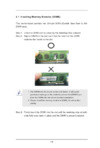
2.1 Installing Memory Modules (DIMM)
This motherboard provides two 204-pin DDR3 (Double Data Rate 3) SO-
DIMM slots.
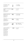
Step 1. Unlock a DIMM slot by pressing the retaining clips outward.
Step 2. Align a DIMM on the slot such that the notch on the DIMM
matches the break on the slot.
1.TheDIMMonlytsinonecorrectorientation.Itwillcause
permanent damage to the motherboard and the DIMM if you
force the DIMM into the slot at incorrect orientation.
2.PleaseinstallthememorymoduleinDDR3_A2slotasrst
priority.
Step 3. Firmly insert the DIMM into the slot until the retaining clips at both
ends fully snap back in place and the DIMM is properly seated.
notch
break
notch
break
Содержание
- Imb a182 1
- User manual 1
- California usa only 2
- Copyright notice 2
- Disclaimer 2
- Contents 3
- Installation 11 3
- Introduction 5 3
- Software support 39 3
- Uefi setup utility 22 3
- Introduction 4
- Package contents 4
- Specifications 5
- Motherboard layout 8
- Com1 com3 rs232 422 485 pin mapping 10
- I o panel 10
- Lan port led indications 10
- Chapter 2 installation 11
- Pre installation precautions 11
- Installing memory modules dimm 12
- Expansion slots pci express slots 13
- Installing an expansion card 13
- Jumpers setup 14
- Atx at mode jumper 15
- Backlight control signal setting jumper 15
- Com port pin9 power setting jumpers 15
- Jgpio_set1 15
- Power loss jumper 15
- 40 pin lvds1 see p no 29 16
- 6 pin blt_pwr1 see p no 5 16
- B l adjust 16
- B l enable 16
- Inverter power control header 16
- Lcd blt vcc 16
- Lvds panel connector 16
- Onboard headers and connectors 16
- Onboard headers and connectors are not jumpers do not 16
- Pin signal name 16
- Place jumper caps over these headers and connectors plac ing jumper caps over the headers and connectors will cause permanent damage to the motherboard 16
- Certificates passwords and 18
- Curity protects digital identi 18
- Data a tpm system also 18
- Front panel audio header 18
- Helps enhance network se 18
- Integrity 18
- Lpc header 18
- Securely store keys digital 18
- This connector supports 18
- This is an interface for the front panel audio cable that allows convenient connec tion and control of audio devices 18
- Ties and ensures platform 18
- Tpm system which can 18
- Trusted platform module 18
- System panel header 19
- This header accommodates several system front panel functions 19
- Chapter 3 uefi setup utility 22
- Introduction 22
- Uefi menu bar 22
- Navigation keys 23
- Main screen 24
- Advanced screen 25
- Cpu configuration 26
- Chipset configuration 27
- Storage configuration 29
- Super io configuration 30
- Acpi configuration 31
- Usb configuration 32
- Hardware health event monitoring screen 34
- Boot screen 35
- Security screen 37
- Exit screen 38
- Chapter 4 software support 39
Похожие устройства
- ASRock IMB-150N Инструкция
- ASRock IMB-150D-PCI Инструкция
- ASRock IMB-150D Инструкция
- ASRock IMB-150 Инструкция
- ASRock IMB-151N Инструкция
- ASRock IMB-151D-WF Инструкция
- ASRock IMB-151D Инструкция
- ASRock IMB-151 Инструкция
- ASRock IMB-152 Инструкция
- ASRock IMB-153 Инструкция
- ASRock IMB-154B Инструкция
- ASRock IMB-154A Инструкция
- ASRock IMB-154 Инструкция
- ASRock IMB-155B Инструкция
- ASRock IMB-155A Инструкция
- ASRock IMB-155 Инструкция
- ASRock IMB-156M Инструкция
- ASRock IMB-156L Инструкция
- ASRock IMB-161-D Инструкция
- Daikin EKMV2C09B7 Инструкция по монтажу
![ASRock IMB-A182P [12/39] Installing memory modules dimm](/img/pdf.png)
