
Airwell HRW 096 Инструкция по эксплуатации онлайн
English
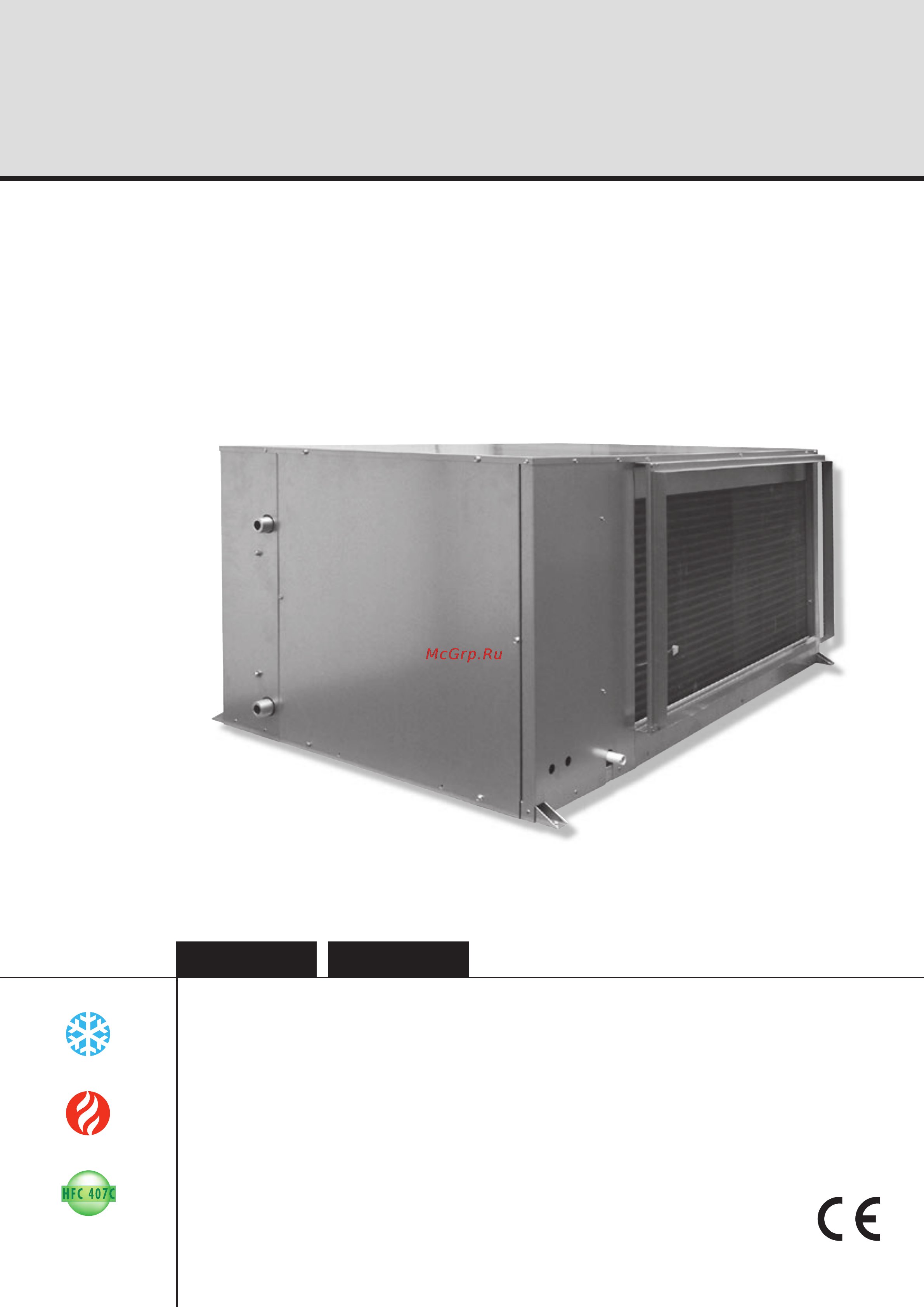
Water source heat pumps
Pompes à chaleur sur boucle d’eau
Installation and maintenance manual
Manuel d’installation et de maintenance
IOM HRW3-N.4GBF
Date : July / Juillet 2007
Supersedes / Annule et remplace : IOM HRW3-N.3GBF/05.07
Français
21.7
30.0 kW
26.6
38.1 kW
HRW
096 & 120
Содержание
- Contents 4
- Ducting and noise level reduction 4
- Electrical connections 7 4
- Final tasks 5 starting recommendations settings 6 4
- General recommendations 4
- Hydraulic connections 1 4
- In warranty return material procedure 2 service and spare parts order 2 4
- Inspection and storage generalities contents of parcel dimensions handling 4
- Installation 4
- Maintenance and servicing 8 4
- Rcl and µbms control modules wiring 8 4
- Return air temperature measurement 2 power failure 2 remote on off make break switch 2 4
- Technical specifications 4
- Wiring diagram and legend 5 4
- Électric spécifications 4
- General recommendations 5
- It is mandatyory to cutoff power supply before starting to 5
- Safety directions 5
- Warning 5
- Work in the electric casing boxes 5
- Contents of parcel 6
- Generalities 6
- Inspection and storage 6
- Dimensions 7
- Handling 7
- Net weight 7
- Air temperature limits 8
- Electrical power supply 8
- Environment 8
- Operating limits 8
- Technical specifications 8
- Water temperature limits 8
- Électric spécifications 8
- Installation 9
- Unit location 9
- Ducting and noise level reduction 10
- Air blowing frame 11
- Connection frame dimensions 11
- Return air intake frame 11
- An outdoor air intake new air may be required for ventilation the blown air temperature must be controlled in order to avoid the temperature of the mixture of outdoor air and return air at the heat pump inlet exceeding the appliance s operating limits it is also common practice to shut down ventilation during periods of inoccupation night time setting of the set temperature 12
- And release a small length 12
- Each appliance s ventilation system is generally a sub system within the building with its own distribution duct network the simple introduction of outdoor air into each return air plenum quite close to the unit s return air intake is sufficient and recommended new air should not be introduced directly into the appliance provide for a sufficient distance to ensure effective mixing of the outdoor air with the return air refer to operating limits 12
- Each unit is supplied with a connection frame also serving as the filter support this enables to filter to be removed from the side without having to dismantle the duct or the connection frame 12
- External static pressure available 12
- Filter access 12
- Fit the fan blower panel 12
- In the same location as the access 12
- Modifying the air blowing direction 12
- Of motor cable 12
- Refit the fan access panel 12
- Refit the top panel 12
- Remove the fan blower panel 12
- Remove the fan motor access panel 12
- Remove the top panel 12
- The flow static pressure adjustment is made with the aid of a variable pulley when adjusting this pulley it is important to ensure that the belt is positioned properly the pulleys belt assembly must be aligned perfectly and the belt tensioned in accordance with best practices 12
- The unit sizes 096 to 120 can be supplied configured for either frontal air blowing known as in line or for side air blowing known as rear it is also possible to modify the air blowing configuration on site to achieve this 12
- Ventilation 12
- Hydraulic connections 13
- Recommendations for hydraulic connections 13
- Recommendations for cleaning and flushing out the system 15
- Protection against freezing 16
- Description of wiring diagram references 17
- Legend 17
- Power supply 17
- See appendix 17
- Wiring diagram 17
- Wiring diagram and legend 17
- Colour code 18
- Pressostats settings 18
- Electrical connections 19
- Generalities 19
- N 400v 50hz 19
- Setting of thermal protection and fuses 19
- Rcl and µbms control modules wiring 20
- X x x x x 21
- X x x x x x x 21
- Μbms and storm 22
- Μbms storm and miu 22
- Appliance configuration 23
- Client settings 23
- Factory configuration 23
- Plug identification 23
- Power failure 24
- Remote on off make break switch 24
- Return air temperature measurement 24
- Rcl only 25
- Zone n 1 25
- Zone n 2 25
- Μbms supervision module 25
- Addressing procedure 26
- N400v 50hz 26
- Final tasks 27
- If needed fix the cables and the pipes on the wall with clamping collars 27
- Initially closed the valve opens 30 seconds before the compressor starts and closes 20 seconds after it stops 27
- Motorised water valve 27
- Operate the air conditioner in the presence of the user and explain all functions 27
- Place the plugs back on the valves and check that they are properly tightened 27
- Show him how to remove clean and place back the filters 27
- The ofan output marked 6 on the storm pcb can be used for a 230 v connection to supply a motorised water valve the valve motor capacity must not exceed 250 watts 27
- When a high or low temperature limit alarm code is activated the compressor stops and the motorised valve closes after 30 minutes the valve re opens for 1 minute to allow for water outlet temperature measurement this operation will be repeated every 30 minutes until the water outlet temperature measurement authorises at logic level the compressor to restart 27
- When this valve is installed on the system it limits main circulation pump energy consumption as well as limiting the overall pressure losses in the hydraulic circuit 27
- Commissioning 28
- Demand for cooling 28
- Starting recommendations settings 28
- Demand for heating 29
- Fan drive system 30
- Fault finding 30
- Maintenance and servicing 30
- Neither the fan nor the compressor operate 30
- Appearance of abnormal noises and vibrations in the casing 31
- Appearance of water droplets in the appliance 31
- Insufficient cooling or heating production 31
- Insufficient water flow at the level of the plate exchanger 31
- Ventilation fan mode operates but the compressor does not operate 31
- Alarm codes 32
- Cooling mode 32
- Lockout if 3 faults within 1 hour cut the mains power supply for 5 seconds and then reconnect 32
- Note more than 2 alarm codes can be activated at the same time only the last code detected will be visible on the rcl control module or on the adapter board after the source of the first alarm code is resolved the second code will appear and so on until all the faults are cancelled and until the led stops flashing 32
- This case only concerns installations where the valve is fitted on the water loop upstream of the machine 32
- Heating mode 33
- Lockout if 3 faults within 1 hour cut the mains power supply for 5 seconds and then reconnect 33
- Low presure 1 bars 33
- Note more than 2 alarm codes can be activated at the same time only the last code detected will be visible on the rcl control module or on the adapter board after the source of the first alarm code is resolved the second code will appear and so on until all the faults are cancelled and until the led stops flashing 33
- The plate exchanger has dual protection to avoid any risk of icing 33
- This case only concerns installations where the valve is fitted on the water loop upstream of the machine 33
- Water temperature too low 8 c 33
- In warranty return material procedure 34
- Service and spare parts order 34
- Appendix annexe anlage allegato anexo 39
- Esquema electrico 39
- Schema eletrico 39
- Schemas electriques 39
- Stromlaufplans 39
- Wiring diagram 39
- Declaración ce de conformidad 41
- Dichiarazione ce di conformità 41
- Déclaration ce de conformité 41
- Ec compliance declaration 41
- Eg konformitätserklärung 41
- Ace industrie 42
- Route de verneuil 27570 tillières sur avre france 42
Похожие устройства
- Airwell HRW 120 Инструкция по эксплуатации
- Airwell HRW 019 Инструкция по эксплуатации
- Airwell HRW 024 Инструкция по эксплуатации
- Airwell HRW 030 Инструкция по эксплуатации
- Airwell HRW 036 Инструкция по эксплуатации
- Airwell HRW 042 Инструкция по эксплуатации
- Airwell HRW 048 Инструкция по эксплуатации
- Airwell HRW 060 Инструкция по эксплуатации
- Airwell HRW 072 Инструкция по эксплуатации
- Aerial AD 550 Инструкция по эксплуатации
- Aerial AD 650 Инструкция по эксплуатации
- Aerial AD 580 Инструкция по эксплуатации
- Aerial AD 110 Инструкция по эксплуатации
- Aerial AD 120 Инструкция по эксплуатации
- Aerial AD 130 Инструкция по эксплуатации
- Aerial AD 150 Инструкция по эксплуатации
- Aerial AP 50 Инструкция по эксплуатации
- Aerial AP 70 Инструкция по эксплуатации
- Aerial AP H 100 Инструкция по эксплуатации
- Aerial AP H 120 Инструкция по эксплуатации
Скачать
Случайные обсуждения