Hikoki CG 27EC [11/292] English
![Hikoki CG 27EC [11/292] English](/views2/1471569/page11/bgb.png)
English
11
4. Adjusting line length
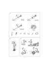
Set the engine speed as low as possible and tap the
head on the ground. The nylon line will be drawn out
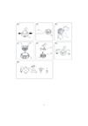
about 3 cm with each tap. (Fig. 12)
Also, you can extend the nylon line by hand but the
engine must be completely stopped. (Fig. 13)
Adjust the nylon line to the proper length of 11–14 cm
before each operation.
Installation of cutting blade
CG24ECP (S) / CG27EC (S) / CG27ECP (S) (Fig. 14)
Insert the alien wrench (17) into the hole of the gear case in
order to lock the shaft.
Assemble in the following order: Cutter holder (A) (18),
blade (19), cutter holder (B) (20), nut cover (21).
Tighten the fi xing nut with the box wrench. Please note that
the cutter fi xing nut (22) has left-handed threads (clockwise
to loosen/ counter-clockwise to tighten).
NOTE
○ When installing cutter holder (B) (20), be sure to set
concave side upward.
○ When installing or removing a blade, make sure to wear
gloves and place the blade cover over the blade.
CAUTION
Check a nut cover (21) for wear or cracks before
operation. If any damage or wear is found, replace it, as
it is an article of consumption.
WARNING
○ When installing a cutting blade, make sure that there are
no cracks or any damage in it and that the cutting edges
are facing the correct direction.
○ Remove any surface grit from blade installation fi ttings
(cutter holder (A) (18), cutter holder (B) (20), nut
cover (21), nut (22)). Failure to do so may result in the
loosening of nuts.
○ The protrusion of the cutter holder (A) (18) may become
misaligned with the blade (19) while tightening nut
(22). Before operation, make sure the blade has been
properly installed. (Fig. 15)
○ Rotate the blade by hand and make sure there is no
rocking or abnormal noise. Rocking may cause abnormal
vibrations or result in the loosening of nuts.
CG24ECMP (S) / CG27ECMP (S) (Fig. 16)
When installing a cutting blade, make sure that there are no
cracks or any damage in it and that the cutting edges are
facing the correct direction.
NOTE
○ When installing cutter holder cap (23), be sure to set
concave side upward.
○ Press the stopper pin (24) of the angle transmission in
order to lock the cutter holder (25). Please note that the
cutter fi xing bolt or nut (26) has left-handed threads,
(clockwise to loosen/ counter-clockwise to tighten).
Tighten the fi xing bolt or nut with the box wrench.
CAUTION
○ Before operation, make sure the blade has been properly
installed.
○ If your unit is equipped with protection cover under a
cutting blade, check it for wear or cracks before operation.
If any damage or wear is found, replace it, as it is an article
of consumption.
○ You have to wear gloves when handling the cutting
blade.
WARNING
For HiKOKI heads, use only fl exible, non-metallic line
recommended by the manufacturer. Never use wire or
wire ropes. They can break off and become a dangerous
projectile.
OPERATING PROCEDURES
Fuel (Fig. 17)
WARNING
○ The trimmer is equipped with a two-stroke engine.
Always run the engine on fuel, which is mixed with oil.
Provide good ventilation, when fueling or handling fuel.
○ Fuel is highly fl ammable and it is possible to get seriously
injured when inhaling or spilling on your body.
Always pay attention when handling fuel. Always have
good ventilation when handling fuel inside building.
Fuel
○ Always use branded 89 octane unleaded gasoline.
○ Use genuine two-cycle oil or use a mix between 25:1 to
50:1, please consult about the mixture ratio to HiKOKI
Authorized Service Centers.
○ If genuine oil is not available, use an anti-oxidant added
quality oil expressly labeled for air-cooled 2-cycle engine
use (JASO FC GRADE OIL or ISO EGC GRADE). Do not
use BIA or TCW (2-stroke water-cooling type) mixed oil.
○ Never use multi-grade oil (10 W/30) or waste oil.
○ Never mix fuel and oil in machine’s fuel tank. Always mix
fuel and oil in a separate clean container.
Always start by fi lling half the amount of gasoline, which is
to be used.
Then add the whole amount of oil. Mix (shake) the fuel
mixture. Add the remaining amount of gasoline.
Mix (shake) the fuel-mix thoroughly before fi lling the fuel
tank.
Mixing amount of two-cycle oil and gasoline
Gasoline (Liter)
Two-cycle oil (ml)
Ratio 50:1 Ratio 25:1
0.5 10 ——— 20
1 20 ——— 40
2 40 ——— 80
4 80 ——— 160
Fueling
WARNING
○ Always shut off the engine and let it cool for a few
minutes before refueling.
Do not smoke or bring fl ames or sparks near the fueling
site.
○ Slowly open the fuel tank, when fi lling up with fuel, so
that possible over-pressure disappears.
○ Tighten the fuel tank cap carefully, after fueling.
○ Always move the unit at least 3 m from the fueling area
before starting.
○ Always wash any spilled fuel from clothing immediately
with soap.
○ Be sure to check any fuel leakage after refueling.
○ Before fueling, in order to remove static electricity from
the main body, the fuel container and the operator,
please touch the ground that is slightly damp.
Before fueling, clean the tank cap area carefully, to ensure
that no dirt falls into the tank. Make sure that the fuel is well
mixed by shaking the container, before fueling.
Starting
WARNING
○ Before starting the tool, ensure that the cutting
attachment is not touching any objects or the ground.
Otherwise, the cutting attachment may unexpectedly
rotate and cause an injury.
000Book_CG24ECP(S).indb 11000Book_CG24ECP(S).indb 11 2017/12/14 9:49:522017/12/14 9:49:52
Содержание
- Cg 24ecp s cg 24ecp sl cg 24ecmp s cg 27ec s cg 27ecp s cg 27ecp sl cg 27ecmp s 1
- English 7
- Meanings of symbols 7
- English 8
- Warnings and safety instructions 8
- What is what fig 1 8
- English 9
- Assembly procedures 10
- English 10
- Specifications 10
- English 11
- Operating procedures 11
- English 12
- English 13
- Maintenance 13
- English 14
- Selecting accessories 14
- English 15
- Selecting cutting attachments 15
- English 16
- Troubleshooting 16
- English 17
- Deutsch 18
- Symbolbedeutungen 18
- Deutsch 19
- Warn und sicherheitshinweise 19
- Was ist was abb 1 19
- Deutsch 20
- Deutsch 21
- Technische daten 21
- Zusammenbau 21
- Deutsch 22
- Betriebsverfahren 23
- Deutsch 23
- Deutsch 24
- Deutsch 25
- Wartung 25
- Auswahl von zubehör 26
- Deutsch 26
- Auswahl der schneid ausrüstung 27
- Deutsch 27
- Deutsch 28
- Fehlerbehebung 28
- Deutsch 29
- Français 30
- Signification des symboles 30
- Description fig 1 31
- Français 31
- Précautions et consignes de sécurité 31
- Français 32
- Caractéristiques 33
- Français 33
- Montage 33
- Français 34
- Français 35
- Utilisation 35
- Entretien 36
- Français 36
- Français 37
- Français 38
- Sélection d accessoires 38
- Français 39
- Sélection d accessoires de coupe 39
- Dépannage 40
- Français 40
- Français 41
- Italiano 42
- Significati dei simboli 42
- Avvertenze e istruzioni per la sicurezza 43
- Descrizione delle varie parti fig 1 43
- Italiano 43
- Italiano 44
- Italiano 45
- Procedure di montaggio 45
- Specifiche tecniche 45
- Italiano 46
- Funzionamento 47
- Italiano 47
- Italiano 48
- Manutenzione 48
- Italiano 49
- Italiano 50
- Scelta degli accessori 50
- Italiano 51
- Selezione dei dispositivi di taglio 51
- Italiano 52
- Risoluzione dei problemi 52
- Italiano 53
- Betekenis van de symbolen 54
- Nederlands 54
- Nederlands 55
- Waarschuwingen en veiligheidsinstructies 55
- Wat is wat afb 1 55
- Nederlands 56
- Montageprocedures 57
- Nederlands 57
- Specificaties 57
- Bediening 58
- Nederlands 58
- Nederlands 59
- Nederlands 60
- Onderhoud 60
- Nederlands 61
- Nederlands 62
- Selectie van toebehoren 62
- Nederlands 63
- Selectie van snijuitrustingen 63
- Nederlands 64
- Problemen oplossen 64
- Nederlands 65
- Español 66
- Significado de los símbolos 66
- Advertencias e instrucciones de seguridad 67
- Descripción de las partes fig 1 67
- Español 67
- Español 68
- Español 69
- Especificaciones 69
- Procedimientos de montaje 69
- Español 70
- Español 71
- Procedimientos de funcionamiento 71
- Español 72
- Español 73
- Mantenimiento 73
- Español 74
- Selección de accesorios 74
- Español 75
- Selección de accesorios de corte 75
- Español 76
- Resolución de problemas 76
- Español 77
- Português 78
- Significado dos símbolos 78
- Advertências e instruções de segurança 79
- Descrição de cada componente fig 1 79
- Português 79
- Português 80
- Especificações 81
- Português 81
- Procedimentos de montagem 81
- Português 82
- Português 83
- Procedimentos de operação 83
- Manutenção 84
- Português 84
- Português 85
- Português 86
- Selecionar acessórios 86
- Português 87
- Selecionar os acessórios de corte 87
- Português 88
- Resolução de problemas 88
- Português 89
- Svenska 90
- Symbolernas betydelse 90
- Svenska 91
- Vad är vad bild 1 91
- Varningar och säkerhetsinstruktioner 91
- Svenska 92
- Montering 93
- Svenska 93
- Tekniska data 93
- Användning 94
- Svenska 94
- Svenska 95
- Svenska 96
- Underhåll 96
- Svenska 97
- Välja tillbehör 97
- Svenska 98
- Välja skärtillbehör 98
- Felsökning 99
- Svenska 99
- Svenska 100
- Betydning af symboler 101
- Advarsler og sikkerhedsinstruktioner 102
- Hvad er hvad fig 1 102
- Samleprocedurer 104
- Specifikationer 104
- Betjeningsprocedurer 105
- Vedligeholdelse 107
- Valg af tilbehør 108
- Valg af skæretilbehør 109
- Fejlfinding 110
- Forklaring av symboler 112
- Advarsler og sikkerhetsinstruksjoner 113
- Hva er hva fig 1 113
- Montering 115
- Spesifikasjoner 115
- Vedlikehold 118
- Velge tilbehør 119
- Velge kutteutstyr 120
- Feilsøking 121
- Symbolien merkitykset 123
- Osien selitykset kuva 1 124
- Varoitukset ja turvallisuusohjeet 124
- Kokoaminen 126
- Tekniset tiedot 126
- Koneen käyttö 127
- Huolto 129
- Varusteiden valitseminen 130
- Leikkuulaitteen valitseminen 131
- Vianmääritys 132
- Eπεξηγηση συμβολων 134
- Ελληνικά 134
- Ελληνικά 135
- Προειδοποιησεισ και υποδειξεισ ασφαλειασ 135
- Τι ειναι τι εικ 1 135
- Ελληνικά 136
- Διαδικασιεσ συναρμολογησησ 137
- Ελληνικά 137
- Τεχνικα χαρακτηριστικα 137
- Ελληνικά 138
- Διαδικασιεσ λειτουργιασ 139
- Ελληνικά 139
- Ελληνικά 140
- Ελληνικά 141
- Συντηρηση 141
- Ελληνικά 142
- Ελληνικά 143
- Επιλογη των αξεσουαρ 143
- Ελληνικά 144
- Επιλογη των εξαρτηματων κοπησ 144
- Αντιμετωπιση προβληματων 145
- Ελληνικά 145
- Ελληνικά 146
- Polski 147
- Znaczenie symboli 147
- Ostrzeżenia i wskazówki bezpieczeństwa 148
- Polski 148
- Zasadnicze podzespoły urządzenia rys 1 148
- Polski 149
- Dane techniczne 150
- Polski 150
- Procedury montażu 150
- Polski 151
- Polski 152
- Procedury robocze 152
- Polski 153
- Konserwacja 154
- Polski 154
- Polski 155
- Wybór akcesoriów 155
- Polski 156
- Wybór akcesoriów do cięcia 156
- Polski 157
- Wykrywanie i usuwanie usterek 157
- Polski 158
- A szimbólumok jelentése 159
- Magyar 159
- Figyelmeztetések és biztonsági óvintézkedések 160
- Magyar 160
- Mi micsoda 1 ábra 160
- Magyar 161
- Magyar 162
- Műszaki adatok 162
- Összeszerelési eljárások 162
- Magyar 163
- Magyar 164
- Működtetési eljárások 164
- Karbantartás 165
- Magyar 165
- Magyar 166
- Magyar 167
- Tartozékok kiválasztása 167
- Magyar 168
- Vágási toldalékok kiválasztása 168
- Hibaelhárítás 169
- Magyar 169
- Magyar 170
- Význam symbolů 171
- Čeština 171
- Co je co obr 1 172
- Varování a bezpečnostní pokyny 172
- Čeština 172
- Čeština 173
- Montážní postupy 174
- Specifikace 174
- Čeština 174
- Pracovní postupy 175
- Čeština 175
- Čeština 176
- Údržba 177
- Čeština 177
- Výběr příslušenství 178
- Čeština 178
- Výběr řezných nástavců 179
- Čeština 179
- Čeština 180
- Řešení problémů 180
- Čeština 181
- Sembolleri n anlamlari 182
- Türkçe 182
- Tanimlar şekil 1 183
- Türkçe 183
- Uyarilar ve güvenli k tali matlari 183
- Türkçe 184
- Montaj i şlemleri 185
- Tekni k özelli kler 185
- Türkçe 185
- Kullanim prosedürleri 186
- Türkçe 186
- Türkçe 187
- Türkçe 188
- Aksesuarlarin seçi lmesi 189
- Türkçe 189
- Kesme eklenti leri ni n seçi lmesi 190
- Türkçe 190
- Sorun gi derme 191
- Türkçe 191
- Türkçe 192
- Română 193
- Sensul simbolurilor 193
- Avertismente și instrucţiuni de siguranţă 194
- Descrierea pieselor fig 1 194
- Română 194
- Română 195
- Mod de asamblare 196
- Română 196
- Specificaţii 196
- Română 197
- Proceduri de operare 198
- Română 198
- Română 199
- Întreţinere 199
- Română 200
- Română 201
- Selectarea accesoriilor 201
- Română 202
- Selectarea atașamentelor de cosire 202
- Depanare 203
- Română 203
- Română 204
- Pomen simbolov 205
- Slovenščina 205
- Opis delov sl 1 206
- Opozorila in varnostna navodila 206
- Slovenščina 206
- Slovenščina 207
- Postopek montaže 208
- Slovenščina 208
- Specifikacije 208
- Postopki upravljanja 209
- Slovenščina 209
- Slovenščina 210
- Slovenščina 211
- Vzdrževanje 211
- Izbira dodatkov 212
- Slovenščina 212
- Izbira priključkov za rezanje 213
- Slovenščina 213
- Odpravljanje težav 214
- Slovenščina 214
- Slovenščina 215
- Slovenčina 216
- Význam symbolov 216
- Slovenčina 217
- Výstrahy a bezpečnostné pokyny 217
- Čo je čo obr 1 217
- Slovenčina 218
- Postupy pri montáži 219
- Slovenčina 219
- Technické parametre 219
- Prevádzkové postupy 220
- Slovenčina 220
- Slovenčina 221
- Slovenčina 222
- Údržba 222
- Slovenčina 223
- Výber príslušenstva 223
- Slovenčina 224
- Výber príslušenstva na rezanie 224
- Riešenie problémov 225
- Slovenčina 225
- Slovenčina 226
- Български 227
- Значение на символите 227
- Български 228
- Кое какво е фиг 1 228
- Предупреждения и инструкции за безопасност 228
- Български 229
- Български 230
- Процедури за сглобяване 230
- Спецификации 230
- Български 231
- Български 232
- Работни процедури 232
- Български 233
- Български 234
- Поддръжка 234
- Български 235
- Избор на аксесоари 235
- Български 236
- Избор на режещи приставки 236
- Български 237
- Отстраняване на проблеми 237
- Български 238
- Srpski 239
- Značenje oznaka 239
- Srpski 240
- Upozorenja i bezbednosna uputstva 240
- Šta je šta sl 1 240
- Srpski 241
- Postupci sastavljanja 242
- Specifications 242
- Srpski 242
- Postupak rada 243
- Srpski 243
- Srpski 244
- Održavanje 245
- Srpski 245
- Izbor pribora 246
- Srpski 246
- Biranje dodataka za sečenje 247
- Srpski 247
- Rešavanje problema 248
- Srpski 248
- Srpski 249
- Hrvatski 250
- Značenje simbola 250
- Hrvatski 251
- Upozorenja i sigurnosne upute 251
- Što je što slika 1 251
- Hrvatski 252
- Hrvatski 253
- Postupci sastavljanja 253
- Specifikacije 253
- Hrvatski 254
- Operativni postupci 254
- Hrvatski 255
- Hrvatski 256
- Održavanje 256
- Hrvatski 257
- Odabir nastavaka 257
- Hrvatski 258
- Odabir nastavaka za rezanje 258
- Hrvatski 259
- Otklanjanje poteškoća 259
- Hrvatski 260
- Значення символів 261
- Українська 261
- Компоненти мал 1 262
- Попередження та правила техніки безпеки 262
- Українська 262
- Українська 263
- Послідовність монтажу 264
- Технічні характеристики 264
- Українська 264
- Українська 265
- Правила експлуатації 266
- Українська 266
- Українська 267
- Техобслуговування 268
- Українська 268
- Вибір обладнання 269
- Українська 269
- Вибір різальних пристроїв 270
- Українська 270
- Виявлення й усунення несправностей 271
- Українська 271
- Українська 272
- Значение символов 273
- Русский 273
- Детали устройства рис 1 274
- Предостережения и инструкции по технике безопасности 274
- Русский 274
- Русский 275
- Порядок сборки 276
- Русский 276
- Спецификации 276
- Русский 277
- Русский 278
- Эксплуатация 278
- Русский 279
- Русский 280
- Техобслуживание 280
- Русский 281
- Выбор принадлежностей 282
- Русский 282
- Выбор режущих насадок 283
- Русский 283
- Поиск и устранение неисправностей 284
- Русский 284
- Русский 285
- 2018 naoto yamashiro european standard manager 290
- A nakagawa corporate offi cer 290
- Deutsch español 290
- English nederlands 290
- Français português 290
- Head offi ce in japan 290
- Hikoki power tools deutschland gmbh 290
- Italiano svenska 290
- Koki holdings co ltd 290
- Representative offi ce in europe 290
- Shinagawa intercity tower a 15 1 konan 2 chome minato ku tokyo japan 290
- Siemensring 34 47877 willich germany 290
- 2018 naoto yamashiro european standard manager 291
- A nakagawa corporate offi cer 291
- Dansk polski 291
- Head offi ce in japan 291
- Hikoki power tools deutschland gmbh 291
- Koki holdings co ltd 291
- Norsk magyar 291
- Representative offi ce in europe 291
- Shinagawa intercity tower a 15 1 konan 2 chome minato ku tokyo japan 291
- Siemensring 34 47877 willich germany 291
- Suomi čeština 291
- Ελληνικά türkçe 291
- 2018 naoto yamashiro european standard manager 292
- A nakagawa corporate offi cer 292
- Code no e99703374 na printed in china 292
- Head offi ce in japan 292
- Hikoki power tools deutschland gmbh 292
- Koki holdings co ltd 292
- Representative offi ce in europe 292
- Română srpski 292
- Shinagawa intercity tower a 15 1 konan 2 chome minato ku tokyo japan 292
- Siemensring 34 47877 willich germany 292
- Slovenčina український 292
- Slovenščina hrvatski 292
- Български русский 292
Похожие устройства
- Hikoki RB 40SA Инструкция по эксплуатации
- Hikoki RB 24EA Инструкция по эксплуатации
- Hikoki CM 75EBP Инструкция по эксплуатации
- Hikoki CM 75EAP Инструкция по эксплуатации
- Cyberpower BU600E Руководство пользователя
- Cyberpower BU600E Техническое описание
- Cyberpower BU1000E Руководства пользователя
- Cyberpower BU1000E Техническое описание
- Cyberpower BR1000ELCD Руководства пользователя
- Cyberpower BR1000ELCD Техническое описание
- Cyberpower BR1200ELCD Руководства пользователя
- Cyberpower BR1200ELCD Техническое описание
- Cyberpower UT650EG Руководства пользователя
- Cyberpower UT650EG Техническое описание
- Cyberpower UT650EIG Руководства пользователя
- Cyberpower UT650EIG Техническое описание
- Cyberpower UT650EIG[F] Руководства пользователя
- Cyberpower UT650EIG[F] Техническое описание
- Cyberpower UTC600E Руководства пользователя
- Cyberpower UTC600E Техническое описание
![Hikoki CG 27EC [11/292] English](/img/pdf.png)

