
Icom ID-880H Инструкция по эксплуатации онлайн
This device complies with Part 15 of the FCC Rules. Operation is
subject to the following two conditions: (1) this device may not cause
harmful interference, and (2) this device must accept any interference
received, including interference that may cause undesired operation.
WARNING: MODIFICATION OF THIS DEVICE TO RECEIVE CEL-
LULAR RADIOTELEPHONE SERVICE SIGNALS IS PROHIBITED
UNDER FCC RULES AND FEDERAL LAW.
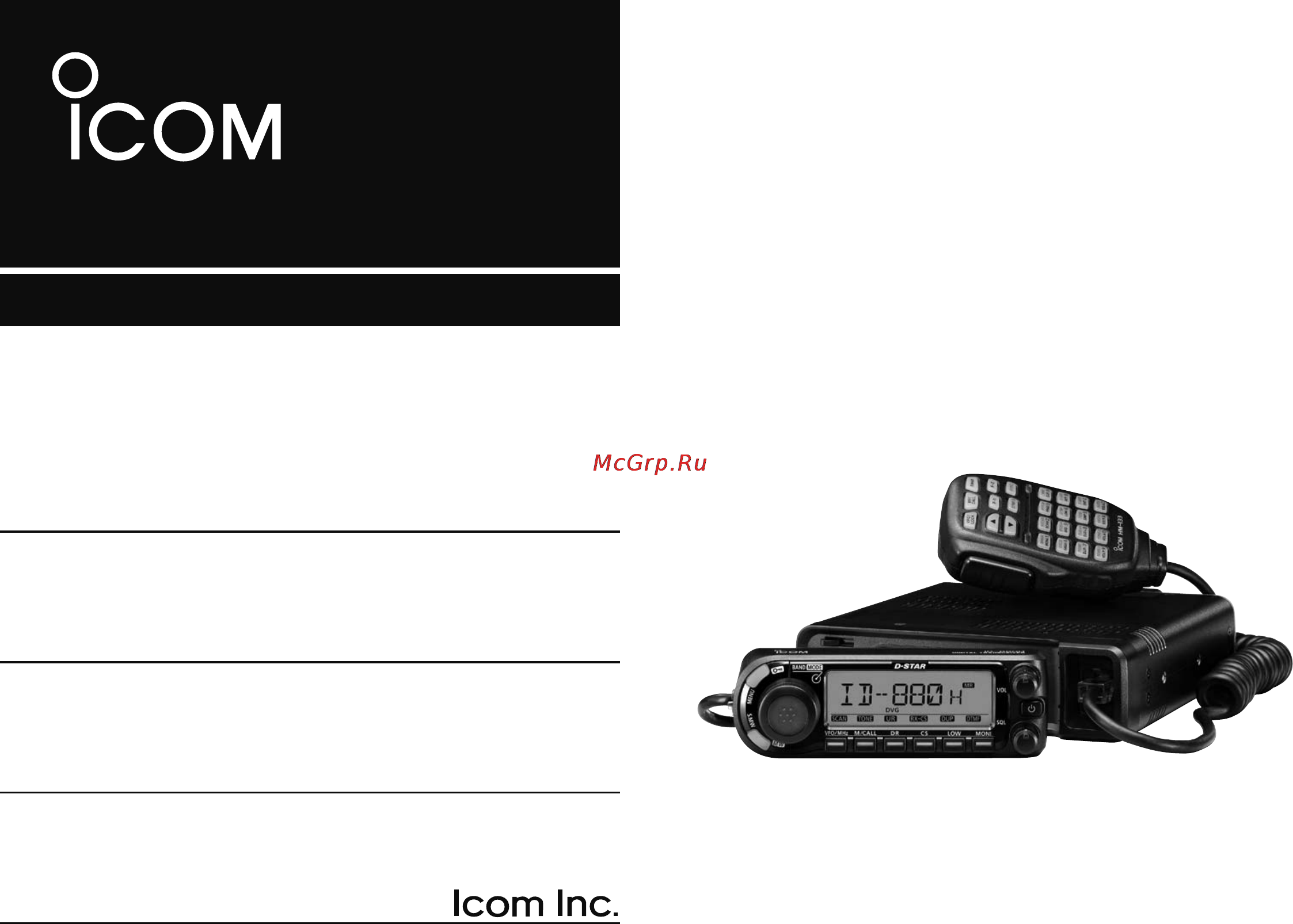
INSTRUCTION MANUAL
ID-880H
VHF/UHF DIGITAL TRANSCEIVER
Содержание
- Id 880h 1
- Instruction manual 1
- Vhf uhf digital transceiver 1
- Detachable controller for flexible installa tion large tuning dial and band switch button 2
- Dr d star repeater mode and repeater list allow you to operate a d star repeater simply switchable vhf and uhf transceiver 50 w high transmit output power 2
- Dv mode digital voice low speed data communication operation ready 2
- Explicit definitions 2
- Features 2
- Foreword 2
- Important 2
- Other than tpe version tpe version 25 w 2
- Read all instruction 2
- Save this instruction manual 2
- Text message and call sign exchange transmitting position data with a third party gps receiver 2
- Be careful 3
- Precautions 3
- R warning neve 3
- R warning rf exposure 3
- Caution 4
- Fcc information 4
- For class b unintentional radiators 4
- Supplied accessories 4
- 2 3 4 5 6 7 8 9 10 11 12 13 14 15 16 17 18 19 5
- Table of contents 5
- Table of contents 6
- 2 3 4 5 6 7 8 9 10 11 12 13 14 15 16 17 18 19 7
- Table of contents 7
- D installation methods 8
- D precaution magnets 8
- Installation 8
- Quick reference guide 8
- Single body installation 8
- D location 9
- Quick reference 9
- Quick reference guide 9
- Remote installation 9
- A microphone connector is available on the main unit front panel connect the supplied microphone connector as illus trated below 10
- D microphone connection 10
- D using the mounting bracket 10
- Q drill 4 holes where the mounting bracket is to be installed 10
- Quick reference guide 10
- W insert the supplied screws nuts and washers through the mounting bracket and tighten e adjust the angle for your suitable position 10
- D controller s attachment detachment 11
- D separation cable connection 11
- Quick reference 11
- Quick reference guide 11
- D remote installation 12
- Quick reference guide 12
- Connecting to a dc power source 13
- Connecting to a dc power supply 13
- D battery connection 13
- D dc power supply connection 13
- Make sure the ground terminal of the dc power supply is grounded 13
- Quick reference 13
- Quick reference guide 13
- R warning never remove the fuse holders from the dc power cable never connect the transceiver directly to a 24 v battery do not use the cigarette lighter socket for power connec tions 13
- See p 165 for fuse replacement 13
- Use a 13 v dc power supply with at least 15 a capacity 13
- Use a rubber grommet when passing the dc power cable through a metal plate to prevent a short circuit 13
- D antenna installation 14
- Quick reference guide 14
- Quick reference 15
- Quick reference guide 15
- Selecting the operating frequency band 15
- Turning on the transceiver 15
- Using the hm 133 15
- Your first contact 15
- Quick reference guide 16
- The tuning dial will allow you to dial in the frequency you want to use page 15 will instruct you on how to set the tuning speed 16
- Tune the frequency 16
- Using the hm 133 16
- You can directly enter the frequency with the hm 133 keypad 16
- Quick reference 17
- Quick reference guide 17
- Repeater operation 17
- Repeater tone 17
- Setting duplex 17
- Using the hm 133 17
- Programming memory channels 18
- Quick reference guide 18
- Selecting a memory channel 18
- Setting a frequency 18
- Using the hm 133 18
- Writing a memory channel 18
- 2 3 4 5 6 7 8 9 10 11 12 13 14 15 16 17 18 19 19
- Main unit 19
- Panel description 19
- Front panel 20
- Panel description 20
- U y t r 0 o i 20
- 0 monitor dtmf key moni dtmf push to turn the monitor function on or off 21
- 1 squelch control sql varies the squelch level 21
- 2 3 4 5 6 7 8 9 10 11 12 13 14 15 16 17 18 19 21
- 2 power key pwr 21
- 4 volume control vol 21
- Adjusts the audio level 21
- Connects the supplied or an optional microphone 21
- During dv mode operation push and hold for 1 sec to enter ur call sign selection state 21
- During dv mode operation push and hold for 1 sec to select the digital call sign squelch digital code squelch and no digital squelch operation in sequence 21
- I call sign rx call sign set key cs rx cs during dv mode operation push to display the current call sign 21
- O output power duplex key low dup each push changes the output power selection 21
- Panel description 21
- Push and hold for 1 sec to enter dtmf set screen 21
- Push and hold for 1 sec to enter the duplex operation selection state 21
- Push and hold for 1 sec to set the received call signs caller and rxrpt1 2 to the current call sign 21
- Push and hold for 1 sec to turn power on or off 3 microphone connector 21
- U dr d star repeater ur key dr ur push to select the dr mode 21
- 1 8 6 4 2 5 3 22
- Function display 22
- Panel description 22
- R t y u 22
- 2 3 4 5 6 7 8 9 10 11 12 13 14 15 16 17 18 19 23
- Panel description 23
- Function guide indicator 24
- Panel description 24
- Q w e r 24
- 2 3 4 5 6 7 8 9 10 11 12 13 14 15 16 17 18 19 25
- Microphone hm 133 25
- Panel description 25
- Key function secondary function key other functions 26
- Microphone keypad 26
- Panel description 26
- 2 3 4 5 6 7 8 9 10 11 12 13 14 15 16 17 18 19 27
- Key function secondary function key other functions 27
- Panel description 27
- Hm 154 28
- Optional microphon 28
- Panel description 28
- 2 3 4 5 6 7 8 9 10 11 12 13 14 15 16 17 18 19 29
- Basic operation 29
- Preparation 29
- Basic operation 30
- D memory mode 30
- D vfo mode 30
- 2 3 4 5 6 7 8 9 10 11 12 13 14 15 16 17 18 19 31
- Basic operation 31
- D call weather channels 31
- D dr d star repeater mode 31
- Basic operation 32
- Push y or z to select the desired frequency 32
- Q rotate dial to set the frequency 32
- Using the tuning dial 32
- Using the y z keys 32
- 2 3 4 5 6 7 8 9 10 11 12 13 14 15 16 17 18 19 33
- Basic operation 33
- Tuning step selection 33
- Using the keypad 33
- Basic operation 34
- D 16key l to turn the microphone keypad lock function on or off 34
- D frequency lock 34
- D microphone keypad lock 34
- Lock functions 34
- Push and hold menu for 1 sec to turn the lock func tion on or off 34
- Push and hold vfo lock for 1 sec to turn the lock function on or off 34
- Push func then 34
- This function locks dial and keys electronically and can be used together with the microphone lock function 34
- This function locks the microphone keypad 34
- To prevent accidental frequency changes and unnecessary function access use the lock function the transceiver has 2 different lock functions 34
- 2 3 4 5 6 7 8 9 10 11 12 13 14 15 16 17 18 19 35
- Basic operation 35
- Receiving 35
- Transmitting 35
- Basic operation 36
- Operating mode selection 36
- Selecting output power 36
- 2 3 4 5 6 7 8 9 10 11 12 13 14 15 16 17 18 19 37
- Basic operation 37
- D squelch attenuator setting 37
- Squelch attenuator 37
- Audio mute function 38
- Basic operation 38
- Monitor function 38
- 2 3 4 5 6 7 8 9 10 11 12 13 14 15 16 17 18 19 39
- Basic operation 39
- One touch ptt function 39
- General 40
- Reference amateur radio handbooks and local ham maga zines for details of local repeaters such as repeater input out put frequencies and locations 40
- Repeater operation 40
- Repeater operation flow chart 40
- Repeaters allow you to extend the operational range of your radio because a repeater has much higher output power than the typical transceiver 40
- Usually a repeater has independent frequencies for receive and transmit the repeater may also require a subaudible tone for access 40
- Accessing a repeater 41
- Repeater operation 41
- Repeater operation 42
- D subaudible tones 43
- Repeater operation 43
- Subaudible tones 43
- D 1750 hz tone 44
- D dtmf tones 44
- Repeater operation 44
- Frequency offset 45
- Repeater operation 45
- Auto repeater 46
- D frequency range and offset direction 46
- Repeater operation 46
- 2 3 4 5 6 7 8 9 10 11 12 13 14 15 16 17 18 19 47
- About the d star system 47
- Dv mode programming 47
- D system description 48
- Dv mode programming 48
- Gateway repeater 48
- Internet network internet network 48
- Link repeater 48
- Zone a 48
- Zone b 48
- 2 3 4 5 6 7 8 9 10 11 12 13 14 15 16 17 18 19 49
- Call sign programming 49
- D your own call sign programming 49
- Dv mode programming 49
- D station call sign programming 50
- Dv mode programming 50
- 2 3 4 5 6 7 8 9 10 11 12 13 14 15 16 17 18 19 51
- D current repeater call sign programming 51
- Dv mode programming 51
- D repeater list contents 52
- Dv mode programming 52
- Repeater list 52
- 2 3 4 5 6 7 8 9 10 11 12 13 14 15 16 17 18 19 53
- Repeater list programming 53
- Dv mode programming 54
- 2 3 4 5 6 7 8 9 10 11 12 13 14 15 16 17 18 19 55
- Dv mode programming 55
- Dv mode programming 56
- 2 3 4 5 6 7 8 9 10 11 12 13 14 15 16 17 18 19 57
- Dv mode programming 57
- Repeater call sign programming call s 57
- Repeater name programming r name 57
- Changing a repeater list 58
- Dv mode programming 58
- 2 3 4 5 6 7 8 9 10 11 12 13 14 15 16 17 18 19 59
- Clearing a repeater list 59
- Call sign group 60
- Current call sign setting 60
- Digital mode operation 60
- Dv mode operation 60
- Quick entry 60
- 2 3 4 5 6 7 8 9 10 11 12 13 14 15 16 17 18 19 61
- D confirming current call sign 61
- Dv mode operation 61
- Receiving a d star repeater 61
- D desired call record indication 62
- Dv mode operation 62
- Received call sign 62
- 2 3 4 5 6 7 8 9 10 11 12 13 14 15 16 17 18 19 63
- D one touch reply using the call record 63
- Dv mode operation 63
- Selecting a call record via rx cal screen 63
- Copying the call sign 64
- D copying the call sign memory contents 64
- Dv mode operation 64
- When auto is set to edit r item 64
- When sel is set to edit r item 64
- 2 3 4 5 6 7 8 9 10 11 12 13 14 15 16 17 18 19 65
- At the same time or individually 65
- D copying the call record contents into call sign memory 65
- Dv mode operation 65
- Into call sign memory 65
- Q enter rx cal rx call sign mode menu rx cal 65
- R push low to enter copy select mode 65
- T rotate dial to select the desired call sign to be copied from c all c ur01 c ur60 c r l and clear 65
- This is a way to copy the call record contents 65
- U push menu to return to frequency indication 65
- W rotate dial to select the desired record channel e push moni several times to select the desired call sign from caller caller s note called rxrpt1 and rxrpt2 65
- Y push moni to copy the selected record s contents into the appropriate call sign memory or repeater lists 65
- D access repeater scan 66
- Dr d star repeater mode is used for d star repeater operation in this mode you can select the pre programmed repeaters and ur call sign by using dial 66
- Dr d star repeater mode operation 66
- Dr mode operation flow chart 66
- Dv mode operation 66
- Q push dr to select the dr mode 66
- W push and hold scan vfo mhz for 1 sec to start the scan 66
- 2 3 4 5 6 7 8 9 10 11 12 13 14 15 16 17 18 19 67
- Dv mode operation 67
- E push dr to toggle the skip setting on or off 67
- Menu rpt l edit l 67
- Skip setting unwanted access repeater can be skipped for rapid selection or scan 67
- W rotate dial to select the desired access repeater to be skipped 67
- Calling cq 68
- Dv mode operation 68
- 2 3 4 5 6 7 8 9 10 11 12 13 14 15 16 17 18 19 69
- Calling cq in another zone different zone cq 69
- Calling cq in the same zone zone cq 69
- Continued instructions from step t on page 50 69
- D calling cq in another area zone cq different zone cq 69
- D calling cq in the same area area cq 69
- Dv mode operation 69
- U push ptt to transmit release to receive 69
- Y push band several times to select grp cq then cqcqcq is selected as ur call sign automatically 69
- Y rotate dial to select a desired repeater name 69
- Calling a specific station 70
- Dv mode operation 70
- 2 3 4 5 6 7 8 9 10 11 12 13 14 15 16 17 18 19 71
- D calling a specific station in the same area area call 71
- D calling a specific station in the same zone zone call 71
- Dv mode operation 71
- Continued instructions from step t on page 52 72
- D calling a specific station in another zone different zone call 72
- Dv mode operation 72
- I push ur dr to exit the linked repeater selection o push ptt to transmit release to receive 72
- Note ote if the other station has accessed the repeater at least once the d star system will connect to the re peater automatically even you don t know where the sta tion is possible in the same area as you or in the same zone or a different zone in this case you select gw as the rpt2 selection the auto gateway setting gw set is helpful p 136 72
- Step 3 rpt2 selection y push and hold ur dr for 1 sec to enter the linked re peater rpt2 selection 72
- U rotate dial to select the preset gateway repeater gw 72
- 2 3 4 5 6 7 8 9 10 11 12 13 14 15 16 17 18 19 73
- D confirming the setting 73
- D one touch reply using the call record in the dr mode 73
- Dv mode operation 73
- D sending cq 74
- Dv mode operation 74
- Simplex operation in the vfo 74
- Ur call sign selection 74
- 2 3 4 5 6 7 8 9 10 11 12 13 14 15 16 17 18 19 75
- D calling a specific station 75
- Dv mode operation 75
- Ur call sign selection 75
- D calling cq in the same area area cq 76
- Dv mode operation 76
- Repeater operation in the vfo 76
- 2 3 4 5 6 7 8 9 10 11 12 13 14 15 16 17 18 19 77
- D calling specific station in the same area area call 77
- Dv mode operation 77
- D calling cq in the same zone zone cq 78
- Dv mode operation 78
- 2 3 4 5 6 7 8 9 10 11 12 13 14 15 16 17 18 19 79
- D calling a specific station in the same zone zone call 79
- Dv mode operation 79
- D calling cq in another zone different zone cq 80
- Dv mode operation 80
- 2 3 4 5 6 7 8 9 10 11 12 13 14 15 16 17 18 19 81
- D calling a specific station in another zone different zone call 81
- Dv mode operation 81
- Available characters 82
- D tx message programming 82
- Dv mode operation 82
- E push low to select the message edit condition 82
- Message operation 82
- Q enter tx msg in messag message screen menu messag tx msg 82
- R rotate dial to select the desired character or symbol 82
- T repeat the step r to enter the desired message 82
- Tx messages are available for up to 5 channels and each channel can be programmed with a message of up to 20 characters 82
- W rotate dial to select the desired transmit message channel 82
- Y push moni to store the message u push menu to return to frequency indication 82
- 2 3 4 5 6 7 8 9 10 11 12 13 14 15 16 17 18 19 83
- D message transmission 83
- Dv mode operation 83
- Automatic reply function 84
- D automatic reply function setting 84
- D rx message indication 84
- Dv mode operation 84
- 2 3 4 5 6 7 8 9 10 11 12 13 14 15 16 17 18 19 85
- Dv mode operation 85
- Emr communication 85
- Break in communication 86
- Dv mode operation 86
- 2 3 4 5 6 7 8 9 10 11 12 13 14 15 16 17 18 19 87
- Dv mode operation 87
- How to use break in 87
- D connection 88
- D low speed data communication application setting 88
- D low speed data communication operation 88
- Dv mode operation 88
- Low speed data communication 88
- 2 3 4 5 6 7 8 9 10 11 12 13 14 15 16 17 18 19 89
- D transmission condition setting 89
- Dv mode operation 89
- D dv auto detect 90
- D packet loss indication 90
- Dv mode operation 90
- Other functions in the dv mode 90
- Gps gps a operation 91
- Gps operation 91
- D sentence formatter setting 92
- Gps gps a operation 92
- 2 3 4 5 6 7 8 9 10 11 12 13 14 15 16 17 18 19 93
- D gps message automatic transmission 93
- D gps message programming 93
- Gps gps a operation 93
- D position indication 94
- D received gps message indication 94
- Gps gps a operation 94
- D displaying direction and forward 96
- D saving own received position data 96
- Gps gps a operation 96
- 2 3 4 5 6 7 8 9 10 11 12 13 14 15 16 17 18 19 97
- Gps gps a operation 97
- D gps data addition 98
- Gps gps a operation 98
- 2 3 4 5 6 7 8 9 10 11 12 13 14 15 16 17 18 19 99
- D gps alarm setting 99
- Gps gps a operation 99
- D gps alarm setting in gps memory channel 100
- Gps gps a operation 100
- 2 3 4 5 6 7 8 9 10 11 12 13 14 15 16 17 18 19 101
- D gps memory clearing 101
- Gps gps a operation 101
- D alarm area 1 102
- Gps gps a operation 102
- 2 3 4 5 6 7 8 9 10 11 12 13 14 15 16 17 18 19 103
- D alarm area 2 103
- Gps gps a operation 103
- 000 i am here can you watch me 104
- D gps a code details 104
- D gps a function 104
- Data extension comment 104
- Gps a code details 104
- Gps a operation 104
- Gps a symbol car 104
- Gps gps a operation 104
- Latitude 104
- Longitude 104
- Time stamp 104
- Time stamp h h m s hour minute second z d h m day hour minute 104
- Unproto address 104
- Your own call sign 104
- 9 10 11 12 13 14 15 16 17 18 19 105
- General description 105
- Memory call channels 105
- C t off to activate the keypad for numeral input c push 3 appropriate digit keys to input a chan nel number 106
- D using the keypad 106
- D using the tuning dial 106
- D using the y z keys 106
- Memory call channels 106
- Q push m call several times to select the memory mode 106
- Selecting a memory channel 106
- W rotate dial to select the desired memory channel 106
- X push 106
- Z push mr call to select the memory mode 106
- Z push mr call to select the memory mode x push y or z to select and set the desired memory channel 106
- Selecting a call channel 107
- Memory call channels 108
- Memory channel programming 108
- 2 3 4 5 6 7 8 9 10 11 12 13 14 15 16 17 18 19 109
- D programming a memory channel via the microphone 109
- Memory call channels 109
- Memory bank setting 110
- Memory call channels 110
- 2 3 4 5 6 7 8 9 10 11 12 13 14 15 16 17 18 19 111
- Memory bank selection 111
- Memory call channels 111
- 0 push and hold mw s mw for 1 sec to set the name and exit channel name programming state 112
- D available characters 112
- E push s mw to enter the select memory write mode 112
- Each memory channel can be programmed with an alpha numeric channel name for easy recognition and can be in dicated independently by channel memory and scan names can be a maximum of 8 characters and bank name can be a maximum of 6 characters 112
- I repeat step u until the desired channel name is pro grammed 112
- Memory call channels 112
- Note only one bank name can be programmed into each bank therefore the previously programmed bank name will be displayed when bank name indication is se lected also the programmed bank name is assigned for the other bank channels automatically 112
- Note scan name indication can be turned on or off in the disp set mode set p 132 112
- Programming memory bank scan name 112
- Q push m call to select the memory mode 112
- T rotate dial to select b name m name or s name when programming the bank name the memory name or the scan name respectively 112
- U rotate dial to select the desired character 112
- W rotate dial to select the desired memory channel 112
- 2 3 4 5 6 7 8 9 10 11 12 13 14 15 16 17 18 19 113
- Memory call channels 113
- Selecting memory bank name indication 113
- Copying memory call contents 114
- D memory call vfo 114
- Memory call channels 114
- 2 3 4 5 6 7 8 9 10 11 12 13 14 15 16 17 18 19 115
- D memory call call memory 115
- Memory call channels 115
- Memory call channels 116
- Memory clearing 116
- 2 3 4 5 6 7 8 9 10 11 12 13 14 15 16 17 18 19 117
- Erasing transferring bank contents 117
- Memory channel operation 117
- Frequency memory skip function 118
- Full scan 118
- Programmed link scan 118
- Programmed scan 118
- Scan operation 118
- Scan types 118
- Selected band scan 118
- 2 3 4 5 6 7 8 9 10 11 12 13 14 15 16 17 18 19 119
- All selected bank scan 119
- Band memory skip scan 119
- Bank link scan 119
- Memory skip scan 119
- Mode memory skip scan 119
- Scan operation 119
- About the scanning steps the selected tuning step in each frequency band in the vfo mode is used during scan 120
- Duplex scan function repeatedly scans two frequencies transmission reception during duplex scan operation 120
- Full band programmed scan 120
- Menu set disp scan 120
- Q push vfo mhz 120
- Scan name can be displayed instead of p link x for pro gram link scan x 0 to 9 progxx for programmed scan xx 0 to 24 when scan name is programmed and set to on in the disp set mode 120
- Scan name is not displayed during scan 120
- Scan operation 120
- T push scan vfo mhz to start the scan 120
- W set the squelch level e push and hold scan vfo mhz for 1 sec to enter the scanning type selection r rotate dial to select the desired scanning type 120
- Scan edges programming 121
- Scan operation 121
- D programming scan edges via the microphone 122
- Scan operation 122
- Memory scan 123
- Scan operation 123
- Memory bank scan 124
- Scan operation 124
- Set the desired bank a to z with dial then push 124
- 10 11 12 13 14 15 16 17 18 19 125
- 2 3 4 5 6 7 125
- D scan start stop via the microphone 125
- Scan operation 125
- T scan again to start the scan b to stop the scan push 125
- T scan c push y z to select the desired scanning type 125
- T scan or 125
- V push 125
- X push 125
- X push and hold y z to start the scan c push y z to stop the scan 125
- Z push vfo lock to select the vfo mode for full band programmed scan push mr call to select the memory mode for memory scan 125
- Z push vfo lock to select the vfo mode for full scan push mr call to select the memory mode for memory scan 125
- Scan operation 126
- Skip channel frequency setting 126
- 2 3 4 5 6 7 8 9 10 11 12 13 14 15 16 17 18 19 127
- D scan pause timer 127
- D scan resume timer 127
- Scan operation 127
- Scan resume condition 127
- D setting pause timer via the microphone 128
- D setting resume timer via the microphone 128
- Scan operation 128
- 2 3 4 5 6 7 8 9 10 11 12 13 14 15 16 17 18 19 129
- Priority watch 129
- Priority watch types 129
- D memory call channel and memory scan watch 130
- Priority watch 130
- Priority watch operation 130
- 2 3 4 5 6 7 8 9 10 11 12 13 14 15 16 17 18 19 131
- D vfo scan watch 131
- Priority watch 131
- D memory call channel and memory scan watch via the microphone 132
- D vfo scan watch via the microphone 132
- Priority watch 132
- 2 3 4 5 6 7 8 9 10 11 12 13 14 15 16 17 18 19 133
- D dr mode vfo watch 133
- Priority watch 133
- D entering menu screen and operation 134
- General 134
- Menu screen operation 134
- 2 3 4 5 6 7 8 9 10 11 12 13 14 15 16 17 18 19 135
- D entering menu screen via the microphone 135
- Example 135
- Menu screen operation 135
- Menu screen indication and arrangement 136
- Menu screen operation 136
- Menu screen shows one of the following indication 136
- 2 3 4 5 6 7 8 9 10 11 12 13 14 15 16 17 18 19 137
- D dup t mode 137
- D dv set mode 137
- D scan mode 137
- D set mode 137
- D ts mode 137
- Items list items list 137
- Menu screen operation 137
- D call s mode 138
- D gps mode 138
- D messag mode 138
- D rpt l mode 138
- D rx cal mode 138
- Menu screen operation 138
- 2 3 4 5 6 7 8 9 10 11 12 13 14 15 16 17 18 19 139
- D frequency offset 139
- D repeater tone frequency 139
- D tsql frequency 139
- Dup t mode items 139
- Menu screen operation 139
- And both r 140
- Available dtcs codes 140
- Both encoder decoder 140
- Code for dtcs squelch operation total of 104 codes 023 754 are available 140
- D digital code 140
- D dtcs code 140
- D dtcs polarity 140
- D dtmf speed 140
- Default 023 140
- Default both n 140
- Menu screen operation 140
- Select the desired dtmf transmission speed from 100 msec 200 msec 300 msec 500 msec 100 100 msec interval 5 characters per second default 200 200 msec interval 2 characters per second 300 300 msec interval 1 characters per second 500 500 msec interval 1 character per second 140
- Selects dtcs 140
- Sets dtcs polarity from both n 140
- Sets the desired digital code for digital code squelch opera tion total of 100 codes 00 99 are available default 00 140
- This item allows you to set the transmit and receive dtcs code polarities independently 140
- Tx normal rx reverse 140
- Tx reverse rx normal 140
- Tx rx normal 140
- Tx rx reverse 140
- 2 3 4 5 6 7 8 9 10 11 12 13 14 15 16 17 18 19 141
- D priority watch 141
- D program skip scan 141
- D scan pause timer 141
- D scan resume timer 141
- Menu screen operation 141
- Scan mode items 141
- D memory bank link function 142
- D weather alert 142
- Menu screen operation 142
- 2 3 4 5 6 7 8 9 10 11 12 13 14 15 16 17 18 19 143
- D program scan link function 143
- Menu screen operation 143
- Menu screen operation 144
- 2 3 4 5 6 7 8 9 10 11 12 13 14 15 16 17 18 19 145
- D attenuator 145
- D mic sens level 145
- D ptt lock 145
- D squelch delay timer 145
- Menu screen operation 145
- Set mode func items 145
- D auto repeater 146
- D busy lockout 146
- D time out timer 146
- Menu screen operation 146
- 2 3 4 5 6 7 8 9 10 11 12 13 14 15 16 17 18 19 147
- D active band 147
- D fan control 147
- D mic up dn 147
- D packet speed 147
- Menu screen operation 147
- D auto dimmer 148
- D auto power off 148
- D data speed 148
- D display dimmer 148
- Menu screen operation 148
- Set mode disp items 148
- 2 3 4 5 6 7 8 9 10 11 12 13 14 15 16 17 18 19 149
- D display color 149
- D lcd contrast 149
- D name indication type 149
- Menu screen operation 149
- D audio filter 150
- D noise filter 150
- D opening message 150
- D scan name 150
- Menu screen operation 150
- Set mode sounds items 150
- D auto reply 152
- D digital monitor 152
- D digital repeater setting 152
- D dv data tx 152
- Dv set mode items 152
- Menu screen operation 152
- 2 3 4 5 6 7 8 9 10 11 12 13 14 15 16 17 18 19 153
- D call sign edit record 153
- D dv auto detect 153
- D repeater call sign auto write 153
- D rx call sign auto write 153
- Menu screen operation 153
- D auto gateway setting 154
- D rx call sign display 154
- D rx message display 154
- D scroll speed 154
- D tx call sign display 154
- Menu screen operation 154
- 2 3 4 5 6 7 8 9 10 11 12 13 14 15 16 17 18 19 155
- D break in function 155
- D emr function 155
- Menu screen operation 155
- D gps set 156
- D gps tx mode items 156
- Gps mode items 156
- Menu screen operation 156
- 2 3 4 5 6 7 8 9 10 11 12 13 14 15 16 17 18 19 157
- Gps a set mode 157
- Menu screen operation 157
- Sentence formatter setting 157
- Menu screen operation 158
- 2 3 4 5 6 7 8 9 10 11 12 13 14 15 16 17 18 19 159
- D gps auto transmission 159
- Menu screen operation 159
- Dtmf memory encoder 160
- Programming a dtmf tone sequence 160
- 2 3 4 5 6 7 8 9 10 11 12 13 14 15 16 17 18 19 161
- D automatic transmission dtmf memory 161
- Dtmf memory encoder 161
- Transmitting a dtmf tone sequence 161
- D manual transmission 162
- D transmitting a dtmf memory directly 162
- Dtmf memory encoder 162
- 2 3 4 5 6 7 8 9 10 11 12 13 14 15 16 17 18 19 163
- Clearing a dtmf memory 163
- Dtmf memory encoder 163
- Dtmf speed 163
- Tone dtcs squelch beep operation 164
- Tone squelch and pocket beep 164
- 2 3 4 5 6 7 8 9 10 11 12 13 14 15 16 17 18 19 165
- D reverse tone dtcs squelch 165
- D setting tone squelch frequency 165
- Tone squelch and pocket beep 165
- A mw to exit the dup t menu screen 166
- Available dtcs codes 166
- Available tone frequencies 166
- B d off c push 166
- D setting dtcs code 166
- Dtcs phase can be selected in dtcs p dtcs polar ity item p 122 166
- E push menu to exit the dup t menu screen 166
- Menu dup t cod 166
- Tone squelch and pocket beep 166
- W rotate dial to select and set the desired dtcs code then push moni 166
- X push y or z to select the desired dtcs code then push 166
- 2 3 4 5 6 7 8 9 10 11 12 13 14 15 16 17 18 19 167
- Dtcs polarity setting 167
- Tone squelch and pocket beep 167
- Tone scan 168
- Tone squelch and pocket beep 168
- 2 3 4 5 6 7 8 9 10 11 12 13 14 15 16 17 18 19 169
- Digital squelch 169
- Tone squelch and pocket beep 169
- D digital code setting 170
- D ur and my call signs setting 170
- Tone squelch and pocket beep 170
- 2 3 4 5 6 7 8 9 10 11 12 13 14 15 16 17 18 19 171
- Microphone keys 171
- Other functions 171
- All reset 172
- Other functions 172
- Partial reset 172
- 2 3 4 5 6 7 8 9 10 11 12 13 14 15 16 17 18 19 173
- Data cloning 173
- D cloning error 174
- D cloning using a personal computer 174
- Other functions 174
- 2 3 4 5 6 7 8 9 10 11 12 13 14 15 16 17 18 19 175
- Auto power off 175
- D data speed 175
- Other functions 175
- Packet operation 175
- Time out timer 175
- D 1200 bps packet operation 176
- D packet jack pin assignment 176
- Other functions 176
- D 9600 bps high speed packet operation 178
- Other functions 178
- 2 3 4 5 6 7 8 9 10 11 12 13 14 15 16 17 18 19 179
- D adjusting the transmit signal output from the tnc 179
- Other functions 179
- D weather alert function 180
- D weather channel selection 180
- Other functions 180
- Weather channel operation 180
- Maintenance 182
- Problem possible cause solution ref 182
- Troubleshooting 182
- 2 3 4 5 6 7 8 9 10 11 12 13 14 15 16 17 18 19 183
- Fuse replacement 183
- Maintenance 183
- D general 184
- D receiver 184
- D transmitter 184
- Specifications 184
- 2 3 4 5 6 7 8 9 10 11 12 13 14 15 16 17 18 19 185
- Specifications 185
- Options 186
- 2 3 4 5 6 7 8 9 10 11 12 13 14 15 16 17 18 19 187
- 2 3 4 5 6 7 8 9 10 11 12 13 14 15 16 17 18 19 189
- 2 3 4 5 6 7 8 9 10 11 12 13 14 15 16 17 18 19 191
- 2 3 4 5 6 7 8 9 10 11 12 13 14 15 16 17 18 19 193
- 1 32 kamiminami hirano ku osaka 547 0003 japan 196
Похожие устройства
- Asus K53E i3-2350M 3G 640G Инструкция по эксплуатации
- Эван ЭПВН 48 Инструкция по эксплуатации
- Icom IC-7100 Инструкция по эксплуатации
- Acer V3-571G-32354G50Mass Инструкция по эксплуатации
- Эван ЭПВН 54 Инструкция по эксплуатации
- Icom IC-7200 Инструкция по эксплуатации
- Asus X54HR-SX287R Инструкция по эксплуатации
- Эван ЭПВН 60 Инструкция по эксплуатации
- Icom IC-7410 Инструкция по эксплуатации
- Lenovo G570 /59319391/ Инструкция по эксплуатации
- Эван В1-6 Инструкция по эксплуатации
- Icom IC-7700 Инструкция по эксплуатации
- Samsung NP355V5C-S08RU Инструкция по эксплуатации
- Dell N5110 /5110-3715/ Инструкция по эксплуатации
- Эван В1-7, 5 Инструкция по эксплуатации
- Icom IC-9100 Инструкция по эксплуатации
- HP Pavilion g6-2168sr Инструкция по эксплуатации
- Эван В1-9 Инструкция по эксплуатации
- Icom IC-A24 Инструкция по эксплуатации
- Packard Bell EASYNOTE TV11HC-52456G50Mnks Инструкция по эксплуатации