Honda CBR929RR — информация о различных аспектах и темах [350/488]
Превью страниц
Страница 350 /
488
![Honda CBR929RR [350/488] Pin with the hole in the handleba](/views2/1121098/page350/bg15e.png)
~
~~~~~~~~~~~~~~~~~~~~~~~~~~~~~~~~~~~~~~~~~~~~~~~~~~~~~~~
~~~~~~~~~~~~~~~~~~~~~~~~~~~~~~~~~~
~
~~~~~~~~~~~~~~~~~~~~~~~~~~~~~~~~~~~~~~~~~~~~~~~~~~~~
~
~~~~~~~~~~~~~~~~~~~~~~~~~~~~~~~~~~~~~~~~~~~~~~~~~~~~~
~~~~~~~~~~~~~~~~~~~~~~~~~~~~~~~~~~~~~~~~~~~~~~~~~
~~~~~~~~~
~
~~~~~~~~~~~~~~~~~~~~~~~~~~~~~~~~~~~~~~~~~~~~~~~~~~~~~
~~~~~~~~~~~~~~
~
~~~~~~~~~~~~~~~~~~~~~~~~~~~~~~~~~~~~~~~~~~~~~~~~~
~
~~~~~~
~
~~~~
~~
~~
~~~~~~
~~~~~~~~~
~~~~
~~~~~~~~~~~~~~~~~~~~~~~~~~~~~~~
~
~~~~~~~~~~~~~~~~~~~~~~~~~~~~~~~~~~~~~~~~~~~~~~~~~~~~
~
~~~~~~~~~~~~~~~~~~~~~~~~~~~~~~~
~~~~
~
~~~~~~~~~~~~~~
~~~
~~~
~~~~~~~~~~~~~~
~~~~~~
~
~~~~~
~~
~~~~~~~~~~~~~
~~~
~~~~~~~~~~
~~
~
~
~
~
~~~~~~
~~~~~~~~~~~~
~
~~~~~~~~~~~~~
Содержание
10895- 1 lubrication seal points
- Cable harness routing
- Emission control information
- Emission control systems
- Formation
- Service rules
- Specifications
- Page 1
- Model identification
- Torque values
- General
- Information
- Genera
- Fhaivml 5eiiial jill r ihe
- Designated color cod
- 5 the color label is attached as show
- 2 the engine serial number is stamped on the right
- The frame serial number is stamped on the
- Safety certification labal
- Right side of the steering hea
- Located on left side of the main frame on the
- 4 the throttle body identification number is
- 3 the vehicle identification number vin is
- Stamped on the intake side of the throttle body as
- Side of the upper crankcas
- Page 2
- Ordering color coded parts always specify the
- Exhaust valve open
- Crankshaft type
- Inverted telescopic fork
- Air filtration
- 395 mm 5
- Cooling system
- 065 mm 8
- Front tire size
- Liquid cooled
- Front suspension
- Chain drive and dohc
- Caster angle
- Rear damper
- Intake valve
- Information
- Firing order
- Bt010r
- Pilot sport e rea
- Imp gal
- Bridgestone
- Pilot sport e
- Hydraulic single disc brake with 1 pot caliper
- Engine dry weight
- Wheelbase
- Bore and stroke
- Paper filter
- Dry weight
- Valve train
- At 1 mm
- Page 3
- Hydraulic double disc brake with 4 pot caliper
- Displacement
- Unit type
- Overall width overall height
- Ground clearance
- Cylinder arrangement
- Trochoid
- Abdc 40 bbdc 20 atdc
- Overall length
- General
- Curb weight
- Trail length
- Oil pum
- Genera
- Tire brand
- 125 mm 4
- Nitrogen gas filled damper 120 70 zr17 58w radial 190 50 zr17 73w radial
- Fuel tank capacity
- States canada type
- Michelin
- Front wheel travel
- Specifications
- Maximum weight capacity
- Compression ratio
- Seat height
- Closes lubrication system
- Rear wheel travel
- Kg 434 ibs 199 kg 439 ibs
- Front brake
- Closes
- Rear tire size
- Kg 379 ibs 174 kg 384 ibs
- Frame type
- Rear suspension
- Kg 353 ibs 164 kg 362 ibs
- Four cylinder inline 30 inclined from vertical
- Forced pressure and wet sump
- California type
- Footpeg height
- Bt01of rea
- Rear brake
- Clutch system
- Clutch operation system
- Lighting system
- Electrical
- Pgm fi programmed fuel injection
- Page 4
- Battery
- Multi plate wet
- Advance
- Ignition system
- Gearshift pattern
- Gear ratio
- Foot operated return system 1
- Final reduction
- Triple phase output alternator
- Drive train
- Transmission
- Constant mesh 6 speed
- Starting system
- Computer controlled digital transistorized with electronic
- Specifications
- Scr shorted triple phase full wave rectification
- Primary reduction
- Charging system
- Cable operated type
- Vacuum difference
- Disassembl
- Recommended engine oil
- Canada
- Purge control solenoid valve resistance at 20 c 68 f
- Cam pulse generator
- Pro honda gn4 or hp4 4 stroke oil
- Pressure
- Body clearanc
- Peak voltage at 20 c 68 f
- A canada or honda 4 stroke
- __engin
- Pair solenoi
- 400 rpm 80 c 176 f
- Viscosit
- Page 5
- 24 k 2
- Oil pump rotor
- 200 100 rpm
- V minimum
- Minimum 10 seconds
- 1 16 1
- Tip clearanc
- Manifold absolut
- System
- Lubricatio
- Standard
- Idle speed
- Specifications
- Generator peak voltage at 20 c 68 f
- General information
- Side clearanc
- Fuel system programmed fuel injection
- Service limit
- Fuel pump flow at 12 v
- Sae 1ow 40
- Cylinder compression
- Cooling system
- Warpage
- Camshaft
- Valve stem
- Cam lobe height
- Valve lifter
- And engine
- Thermostat
- Standard
- Specifications
- Service limit
- Runout
- Reserv
- Recommended antifreeze
- Page 6
- Outer in e
- General information
- Cylinder head valves
- Alternator starter clutch
- Warpage
- 20 3 8 13 16
- Standard
- Service limit
- Page 7
- Onnectin
- Measurement poin
- Mainshaf
- Information
- I_13 mm
- Groove clearanc
- Genera
- Cylinder
- Crankcase piston cylinder
- Connectin
- Clutch gearshift linkage
- Bushing
- Transmission
- Standard
- Service limit
- Runout
- Page 8
- Mainshaft
- Main journal oil clearance
- Information
- Genera
- Gear to bushing
- Crankshaft transmission
- Crankshaft
- Countershaf
- Clutch outer guide i
- Clearance
- Bushing to shaft
- Front wheel suspension steering
- Wheel rim runout
- Pre load
- Va8 c1
- Page 9
- Up to maximum weight capacit
- Minimum tire thread depth
- Up to maximum weigh
- Lepgth___
- Th groove
- Kgf cmz
- Tensio
- Kgf cm
- Steering head bearin
- General information
- Standard
- From full hard
- Spring
- Fluid capacity
- Shock absorber
- Drive chain
- Service limit
- Cold tire pressure
- Runout
- Capacity
- Rk gb50hf
- Rear wheel suspension
- Axle runout
- Radial
- Adjuster standard positio
- With the tapered end facin
- Pro honda suspension fluid ss 8
- 009 imp oz
- Spark plug
- Dot 4 75 30
- _master piston
- Normal
- Disc thickness
- _master cylinder
- Needs charging_
- Voltage 20 c 68 f
- Minimum
- Curren
- V minimum
- Master piston
- Coil peak voltag
- Upper lower
- Master cylinder
- Charging current
- Standard
- Leakage
- Charging coil resistance 20 c 68 f
- Specified brake fluid
- Kw 5 000 rpm
- Capacity
- Specifie
- Iuh27d denso iuh24d denso
- Caliper piston
- Specifications
- Ignition system
- Calipe
- Ignition pulse generator peak voltage ignition timin
- Btdc at idle
- Spark plu
- Ickness brake disc runout
- Brake peda
- Service limit
- Hydraulic brake
- Below 1
- Runout
- Honda dot 4 brake fluid
- Battery charging system
- Height
- Battery
- Piston
- General information
- Alternator
- Page 10
- Fully charged
- Optional
- Neutral indicator oil pressure indicato
- Malfunctio
- Main fuse
- _sub fuse
- Lights meters switches
- V m nimum
- Led led led led led 30a
- V 32 3 cp 23 8 w
- Instrument light
- V 21 5
- Indicator lamp
- Thermo sensor resistance
- Tachometer peak voltage
- Headlight
- Stop to open
- General information
- Starter motor brush length
- Fuel reserve indicator
- Standard
- Front turn signal running light
- Specifications
- Fan motor
- Service limit
- Electric starter
- Rear tur
- Beam indicator
- Pgm fi fuse
- 97 c 19
- Page 11
- 102 c 20
- And nut
- Throttle body insulator band screw
- Oil cooler mounting bolt
- Fuel pipe mounting bolt
- Aloc bol
- Thread
- Note 9 note 9
- Fastener type
- Thermostat cover flange bolt
- Note 9 note 2 note 6
- Fast idle wax unit mounting screw
- Starter valve synchronization plate screw
- Note 3
- Fast idle wax unit link plate screw 1 3
- Starter valve lock nut
- Note 1
- Engine mountin
- Spark plug
- Mm screw
- Engine
- See page 1 14
- Mm hex bolt and nut 6 mm hex bolt and nut
- Ect engine coolant temperature thermosensor
- Mm hex bolt and nut
- Drive sprocket special bolt
- Replace with a new on
- Mm flange bolt and nut
- Ct bolt
- Remarks
- Mm flange bolt 8 mm head
- Cooling syste
- Water pump cover flange bolt
- Pressure regulator mounting bolt
- Mm flange bolt 10 mm head
- Apply sealant to the thread
- Vacuum joint plug bolt for synchronization
- Page 12
- Maintenanc
- Apply oil to the threads and flange surfac
- Torque values
- Others should be tightened to standard torque values listed above
- Apply molybdenum disulfide oil to the threads and seating serface after removing anti rus
- Torque specifications listed below are for important fasteners
- Oil pump driven sprocket bolt
- Lubrication syste
- Apply grease to the threads
- Torque
- Oil pump assembly flange bolt
- Item q ty
- Apply clean engine oil to the o rin
- Timing hole cap
- Oil pressure switch wire terminal screw
- General information
- Apply a locking agent to the threads
- Throttle cable bracket mounting bolt
- Oil pressure switch
- Fuel system programmed fuel injection
- Shift drum stopper arm pivot bolt
- Clutch gearshift linkag
- Note 2 note 2 note 5 note 2 note 5
- Clutch center lock nut
- Note 2
- Note 10 note 2 note 2 note 2 note 2
- Camshaft holder flange bolt
- Upper crankcase sealing bolt
- Mm main journal bolt
- Cam sprocket bolt cam pulse generator rotor dowel bolt
- Stator mounting socket bolt
- Mainshaft bearing set plate bolt
- Cam chain tensioner pivot socket bolt
- Starter one way clutch socket bolt
- Lower crankcase sealing bolt 20 mm
- Cam chain guide mounting socket bolt
- Gearshift return spring pin
- Breather plate flange bolt
- Shift drum center socket bolt
- Cylinder head valve
- Alternator wire clamp socket bolt flywheel flange bolt
- Shift drum bearing shift fork retaining bolt washer
- Cylinder head stud bolt exhaust pipe stud bolt
- Alternator starter clutc
- See page 1 14
- Cylinder head sealing bolt
- Pair reed valve cover flange bolt
- Cylinder head mounting bolt cylinder head mounting socket bolt washer
- Page 13
- Cylinder head cover bolt
- Crankcase piston cylinde
- Note 9
- Crankcase bolt 10 mm
- Note 5 note 2 note 2 note 2
- Connecting rod nut
- Note 5
- Clutch spring bolt washer
- Note 4 5
- Ignition pulse generator rotor mounting bolt
- Exhaust pipe stud bol
- Electri
- Starter motor terminal nut
- Starte
- Remarks
- Page 14
- Note 5
- Neutral switch
- Lights meters switche
- Insulator clamp throttle body side
- Insulator clamp cylinder head side
- Ignition syste
- Note 8
- Lower cowl pan screw
- Engine hanger nut middle
- Side stand bracket bolt
- Engine hanger nut front
- Sensor
- Lower bracket mounting pinch bolt
- Cooling syste
- See tightening sequence below
- Lower bracket mounting nut
- Cooling fan nut
- Seat rail mounting bolt 8 mm
- Inner panel pan screw inner middle cowl pan screw
- Clutch gearshift linkag
- Remarks
- General information
- Bank sensor
- Rear engine hanger pinch bolt
- Fuel system programmed fuel injection
- Rear cowl truss screw
- Fuel pump mounting nut
- Pillion seat mounting nut
- Frame body panels exhaust syste
- Pillion seat bracket mounting bolt nut
- Fan motor nut
- Pillion footpeg mounting socket bolt
- Exhaust valve pulley nut
- Page 15
- Exhaust valve pulley cover mounting bolt lower
- Upper cowl stay mounting bolt
- Exhaust valve mounting bolt
- Note 7
- Exhaust valve cover mounting bolt
- Torque
- Middle cowl pan screw
- Exhaust pipe joint flange nut
- Thread
- Main footpeg mounting bolt
- Engine mountin
- Side stand pivot lock nut
- Main footpeg bracket mounting socket bolt
- Engine hanger nut rear
- Side stand pivot bolt
- Swingarm pivot pinch bolt
- Pad pin plug
- Front brake caliper mounting bolt
- Note 8 note 8
- Front axle holder pinch bolt
- Swingarm pivot nut
- Note 8
- Fork top bridge pinch bolt
- Steering stem nut
- Note 7 note 8 note 7 note 7 note 7 note 7 note 7
- Fork center bolt
- Side stand switch mounting bolt
- Note 7
- Fork bottom bridge pinch bolt
- Shock link nut frame side
- Note 2
- Fan motor switch
- Shock arm plate nut
- Driven sprocket nut
- Remarks
- Note 1
- Caliper body assembly torx bolt pad pin
- Rear wheel suspension
- Lights meters switche
- Brake lever pivot nut
- Rear shock absorber upper mounting nut
- Ignition switch mounting one way bolt
- Brake hose oil bolt
- Rear master cylinder push rod nut
- Hydraulic brak
- Brake caliper bleeder
- Rear master cylinder hose joint screw
- Handlebar weight mounting screw
- Rear brake hose clamp screw
- Handlebar pinch bolt
- Rear brake disc mounting bolt
- Front wheel suspension steerin
- Torque
- Rear brake caliper pin bolt main
- Front brake switch screw
- Top thread a top thread b
- Rear axle nut
- Front brake master cylinder cup mounting nut
- Thread
- Page 16
- Front brake disc mounting bolt
- Peak voltage adaptor
- Km90401
- Driver attachment b driver shaft assembly
- 3710001
- Km90100 07946 km90200 07946 km90300
- Driver attachment a
- 14 14 14 12 12 14
- Page 17
- Km90001
- Driver 40 mm
- 07916 3710100
- Oil pressure gauge set
- Km30101
- Driver
- Vmf kz30200
- 07914 3230001
- Oil pressure gauge attachment
- Ka50100
- Clutch center holder
- Valve spring compressor attachment
- 0050002 07725 0040000
- Note 5
- Interior cutter 26 mm 60 ex
- Can be used with the
- Valve spring compressor
- 0040800 07746 0050100 07746 0050800 07749 0010000 07757 0010000
- Note 1
- Bearing remover shaft
- Valve seat cutter
- 0040002 07506 3000000
- Not available in
- Hgj 0020100
- Bearing remover head 25 mm
- Tool number
- 0020001
- Newly provided too
- Haa pj70100
- Bearing remover b
- Steering stem socket
- 0010800 07746 0010900 07746 0030100 07746 0030300 07746 0040400 07746 0040600
- Newly designed too
- General information
- Bearing remover a
- Steering stem driver
- 0010600
- Mm 45 ex
- Fuel pressure gauge
- Ball race remover set
- Snap ring pliers
- 0010400 07746 0010700
- Mj00100
- Following combination
- Seat cutter 29 mm 45 in
- 0010300
- Me90200
- Flywheel puller
- Attachment 42 47 mm attachment 52 x 55 mm
- Sa50001
- 0010100 07780 0010300 07780 0012000 07780 0012900 07780 0014500 07780 0014000
- Ma70000
- Flywheel holder
- Attachment 30 mm
- Remarks
- Ma60000
- Flat cutter 25 mm 32 ex
- Attachment 24 x 26 mm attachment 22 x 24 mm attachment 40 x 42 mm
- Pilot 17 mm pilot 25 mm pilot 35 mm
- M b00000
- Equivalent commercially available in
- Assembly base
- Peak voltage tester
- Km90500 07946 km90600
- Driver attachment handle
- 3710101
- Note 5 note 5 note 5 note 5
- Driver attachment 25 x 3
- Note 5 note 4
- Description
- Note 3
- Compression gauge attachment
- Note 2
- Needle bearing remover
- N m d kz3010a
- N m d kz30101
- Mad pr90200
- Lmc kv30100
- Ymz 0010100
- Kmd kz30100 with
- Ymf mcjo100 07ymf mcj0200 07ymf mcj0300 07ymf mcj0400
- H m h m loo10a
- Ym b mcf0101
- Valve guide driver
- H m h m l00101
- Tappet hole protector
- General information
- Remover 14 x 16 mm
- Fork damper holder
- R mj my50100
- Ecu test harness
- Page 18
- Driver pilot 32 50 mm
- Page 19
- Crankshaft thrust surface
- Connecting rod small end inner surface
- Connecting rod nut threads
- Connecting rod bearing surface
- Clutch outer primary driven gear sliding surface
- Sealant
- Camshaft lobes journals and thrust surface
- Remarks
- Page 20
- Camshaft holder bolt threads and seating surface
- Material
- Main journal bearing surface
- Main journal 9 mm bolt threads and seating surface
- General information
- Flywheel bolt threads and seating surface
- Engine cont d
- Each gear teeth and rotating surface
- Each 0 ring
- Cylinder head semi circular cut out
- Genera
- Coating widt
- Cam sprocket bolt threads
- Cam chain guide a mounting bolt threads
- Timing hole cap threads
- Page 21
- Multi purpose grease
- Locking agent
- Information
- Rear master cylinder hose joint screw threads
- General information
- Rear master cylinder boot inside and push rod tips
- Fork cap o ring
- Rear brake pedal pivot sliding area
- Footpeg sliding area
- Variable exhaus
- Rear brake calipe
- Equivalent
- Valve cable a b casing inner
- Radiato
- Driven sprocket stud bolt threads
- Pin surface
- Dot 4 brake fluid
- Swingarm pivot dust seal lips
- Page 22
- Clutch cable casing inner
- Swingarm pivot bearing
- Multi purpose grease
- Cable lubricant
- Surface
- Motor switch threads
- Brake pip
- Steering stem top thread
- Molybdenum paste
- Brake master cylinder cups
- Steering head bearing sliding surface
- Molybdenum
- Absorber spring adjuster cam surface
- Silicon grease
- Side stand pivot surface
- Material
- Shock absorber needle bearing shock absorber dus
- Locking agent
- Shell alvania ep2 or
- Location
- Rubber inside
- Honda bon
- Remarks
- Handle gri
- Connectors
- Combination meter
- Cable harness routing
- Right handlebar
- Page 23
- Natural connector
- Multi connector
- Front brake hose
- Signal wire
- Rightturn
- Page 24
- Left turn signal wire
- Left handlebar
- Inside
- Horn wire
- Headlight sockets
- General information
- Fan motor wire
- Clutch cable
- White tape
- Throttle cables
- Switch wire
- Throttle cables
- Switch wire
- Right handlebar
- Page 25
- Meter sub harness
- General information
- Clutch cable
- Page 26
- Page 27
- Page 28
- Overflow tube
- Lower radiator hose
- Bypass hose
- Water pump hose
- Thermostat housing to
- Page 29
- Page 30
- Red connector
- Pressure regulator
- Page 31
- P gray connector
- P blue connector
- Map sensor
- Ignition pulse
- Iat sensor
- Generator2p
- Fuel injector sub harness
- Engine sub harness
- Ect sensor
- Throttle sensor
- Sensor wire
- R _lly
- Page 32
- Fuel tank overflow tube
- Fuel pump reserve sensor
- Fuse box
- Starter relay switch
- Service check connector
- Page 33
- Natural connector
- Main wire harness
- Fuel cut relay
- Engine stop relay
- Connector
- Bank angle sensor
- Page 34
- General information
- P black connector
- Natural connector
- Generator wire
- Vehicle speed sensor
- General information
- Variable intake valve
- Exhaust gas control valve
- Throttle cables
- Evap purge control solenoid valve
- Throttle
- Engine sub harness
- Switch
- Crankcase
- Sub harness
- Control cables
- Starter motor ground cable
- Control cable
- Starter motor cable
- Cam pulse generator 2p
- Sensor 4p natural connector
- California typ
- Sensor
- Breather tube
- Pair control solenoid valve
- Alternator wire
- Page 35
- P natural connector
- Page 36
- General information
- Fuel tank overflow tube
- Sensor wire
- Throttle sensor
- Page 37
- Page 38
- Page 39
- Air cleaner housing
- Throttle body
- Page 40
- Emissio
- Control systems
- The pair control valve is operated by the solenoid valv
- Except idle speed adjustment with the throttle stop scre
- The exhaust emission control system is separate from the
- Ect iat tp map sensor and engine revolution
- The exhaust emission control system is composed of a lean fuel injection setting and no adjustments should be made
- Crankcase emission control system
- The exhaust emission control system consists of a secondary air supply system which introduces filtered air into the exhaust gases in the exhaust por
- California typ
- The engine s exhaust to carbon dioxide co2 dinitrogen
- And water vapo
- Air cleaner housing
- The california type also equipped two three way warm up catalytic converters a three way catalytic converter and a heated
- Solenoid valve is controlled by the pgm fl unit and the fresh air passage is opened closed according the running condition
- Recommende
- Pair control valve
- Pair check valve
- Page 41
- Through chemical reactions they convert hc co and nox in
- Oxygen senso
- Throttle body
- No adjustments to the secondary air supply system should be made although periodic inspection of the components is
- This charge of fresh air promotes burning of the unburned exhaust gases and changes a considerable amount of
- No adjustment to these systems should be made although periodic inspection of the components is recommende
- The three way catalytic converters are in the exhaust syste
- Hydrocarbons and carbon monoxide into relatively harmless carbon dioxide and water vapo
- The reed valve prevents reverse air flow through the syste
- Fresh air is drawn into the exhaust port by the function of the pair pulse secondary air injection control valv
- Fuel vapor from the fuel tank is routed into the evaporative emission evap canister where it is absorbed and stored while
- When the engine is running and the evaporative emission evap purge control solenoid valve is open
- Fuel vapor
- Throttle body
- Fuel tank
- This model complies with california air resources board evaporative emission requirement
- Fresh air
- Thereo
- Evap purge control valve
- The engine is stoppe
- Evap canister
- Tampering with the noise control system is prohibite
- Design has been removed or rendered inoperative by any person
- Replacing any moving parts of the vehicle or parts of the exhaust or intake system with parts other than those specified
- By the manufacture
- Replacement of any device or element of design incorporated into any new vehicle for the purpose of noise control prior to
- Among those acts presumed to constitute tampering are the acts listed below
- Removal of or puncturing of the muffler baffles header pipes or any other component which conducts exhaust gase
- 2 the use of the vehicle after such device or element of
- Removal of or puncturing of any part of the intake syste
- 1 the removal or rendering inoperative by any person other than for purposes of maintenance repair or
- Page 42
- Local law prohibits the following acts or the causing
- Lack of proper maintenanc
- Its sale or delivery to the ultimate purchaser or while it is in us
- Fuel vapor in the evap canister is drawn into the engine through the throttle body
- Pair check valve
- Air cleaner housing cover as show
- Page 43
- Page 3 4 for fuel tank openin
- On the storage compartment as show
- Label california type only
- Vacuum hose routing diagram label
- It gives base tune up specification
- Vacuum hose routing diagram
- Information
- To open
- General information
- To acl
- Forward
- Throttle bcdy
- Evaporative family
- The vacuum hose routing diagram label is on the
- The seat must be removed to read i
- Engine family i
- The fuel tank must be opened to read i
- Emission control information label
- Solenoid
- Control
- Sensor
- Canister
- Refer to
- California vehicle
- Pressure regulate
- An emission control information label is located
- Windscreen
- Page 44
- Lower cowl
- Frame body panels exhaust system
- Page 1
- Remove the two seat mounting socket bolts behind
- Remove the seat see above
- Remove the rear cowl setting bolts collars
- Remove the mounting collar
- Pillion seat rear cowl
- Pillion seat
- Page 2
- Open the pillion seat using the ignition ke
- Install the mounting collars into the seat brackets
- Install and tighten the socket bolts securely
- Ignition key
- The sea
- Collar
- Spacer
- As shown
- Slide the seat back and then of
- And install the sea
- Setting bolt
- Align the seat hook with the fuel tank rear bracket
- Rjj on
- Previous ste
- Pillion seat
- Page 3
- Nuts then remove the pillion seat bracket as an
- Note that these
- Disconnect the rear brake tail light connector
- Trim clip
- Carefully spread the bottom of both sides of the
- Thim clips are slightly different
- Brake tail light connectors
- Than those
- Bolt nut
- Assembly
- Return spring
- Assembl
- Removed in the
- Remove the two trim clips under the rear cow
- Remove the two trim clips and two retaining
- Remove the pillion seat bracket mounting bolts
- Rear cowl then remove it from the seat rai
- Rear cowl
- Install the rear cowl over the side rail being careful
- Install the lower trim clip
- Install and tighten the mounting screws to the speci
- Gently spread the
- Frame body panels exhaust system
- Fied torqu
- Trim clip
- The regulator
- Sides to fit over
- Rectifie
- Pillion seat assembly
- Page 4
- Not to damage the wire harnes
- Install the two trim clips
- Middle lower cowl
- Install the spacers setting collars and setting bolts
- Install the pillion seat bracket assembly onto the
- Hold the bolt and tighten the nut to the specified
- Frame body panels exhaust system
- Connect the rear brake tail light connector
- Trim clips
- Check the return spring hook position then install
- Then tighten the bolts securel
- Brake tail light connectors
- The bracket mounting bolts nuts
- Setting bolt
- Seat rai
- Route the wire harness and clamp it as show
- Remove the trim clips from the inner middle cowl
- Removal
- Pillion seat
- Page 5
- Lower cow
- Grommet then remove the middle cow
- Grommet
- Frame body panels exhaust system
- Bolt and inner
- And left lower cowl
- Special bolts
- Special bolt
- Right lower
- Remove the two trim clips and separate the right
- Remove the two screws special
- Remove the six screws and special bol
- Remove the lower cowl assembly from the right
- Remove the four special bolt
- Release the middle cowl boss from the inner panel
- Page 6
- Install and tighten the inner lower cowl screw to the
- Inner middle cowl
- Inner lower cowl
- Ends of the inner
- Cowl groove
- The inner lower
- Assemble the inner lower cowl right and left lower
- Specified torqu
- Right lower
- Page 7
- Middle cowl into
- Middle cowl
- Lower cowl
- Left lower cowl
- Install the two trim clips and special bol
- Install the lower cowl onto the frame from the right
- Install bottom
- Install the middle cowl while aligning its boss with
- Install and tighten the special bolt
- Grommet
- Frame body panels exhaust system
- Four trim clip
- Trim clips
- Tighten the special bol
- Tighten the screws to the specified torque
- The inner panel grommet
- Special bolts
- Special bolt
- Secure the inner lower cowl and middle cowl using
- Page 8
- Install the special bolt and screw
- Remove the middle cowl pag
- Rear view mirror
- Page 9
- Inner panel
- Heat guard
- From the upper cowl
- Windscreen
- And rearview mirror
- Washers
- Upper cowl
- Socket bolts
- Screws
- Remove the two trim clips from the inner panel
- Remove the screws washers and windscree
- Remove the screw and then remove the inner panel
- Remove the screw and heat guard on both sid
- Remove the rearview mirror mounting socket bolts
- Pull the upper cowl forward
- Page 10
- Front turn signal uni
- Frame body panels exhaust system
- Disconnect the headlight sockets and turn signal
- Connectors then remove the upper cow
- Washer
- Setting plate
- Screws
- Remove the upper cowl mounting bolt and washe
- Remove the screws and air guar
- Remove the nut and setting plate then remove the
- Page 11
- Install the upper cowl onto the upper cowl stay
- Install the air guard and tighten two screw
- Install and tighten the nut securel
- Groove as show
- Grommets
- Frame body panels exhaust system
- While aligning the headlight unit bosses with the
- Connector and turn signal connector
- Upper cowl stay grommet
- Connect the headlight connectors position light
- Screws
- And wires properly
- Route the turn signal wire into the upper cowl in
- Route the turn signal wire into the inner middle
- Route the harness
- Place the upper cowl onto the upper cowl stay
- Page 12
- Page 1 23
- Ner middle cowl and setting plat
- Install the washer and upper cowl mounting bolt
- Install the rearview mirror and tighten the socket
- Install the heat guard onto the inner middle cowl
- Install and tighten the screw to the specified torqu
- Heat guard
- Aligning its tab with the hole in the inner middle
- With screw
- Windscreen
- Tighten the upper cowl mounting bolt securel
- Socket bolts
- Screws
- Rear view mirror
- Page 13
- Install the windscreen and washers then secure it
- Install
- To the specified torqu
- Inner panel
- The inner
- Inner middle cowl
- Special bolts
- Secure the inner panel and inner middle cowl with
- Front fender
- Remove the front fender mounting special bolts
- Disconnect the turn signal connectors and license
- Remove the front fender forwar
- Clamp nut
- Remove the followin
- Battery page 16 5
- Remove the brake hose clamp mounting nuts
- And reflector
- Reflector
- Rear fender
- Rear cowl page 2 2
- Page 14
- Light connecto
- License light connector
- Installation is in the reverse order of remova
- Two trim clip
- Install and tighten the inner panel mounting screw
- Turn signal connectors
- Release the regulator rectifier wire and main wire
- Regulator rectifier wire
- Page 15
- Harness from the seat rail and rear fende
- Fuel cut relay
- Frame body panels exhaust system
- Disconnect the rear brake light switch 2p natural
- Disconnect the ecm engine control module multi
- Disconnect the alternator 3p natural connector
- Connectors them remove the ecm page 5 89
- Connectors
- Connecto
- Unhook the retaining tab and remove the fuse box
- Collar
- Starter relay
- And regulator rectifier 4p natural connecto
- Remove the two rear fender mounting bolts and
- Remove the starter relay switch from the rear
- Remove the fuel cut relay from the rear fende
- Fmil 3race
- Rear bracket
- Page 16
- Page 1 23
- Ness properly
- Installation
- Install the rear fender by aligning its lower groove
- Fuse box
- Fuel tank
- With the seat rail brac
- While installing
- Frame body panels exhaust system
- Unhook the rear fender from the seat rail brace
- Then remove the rear fender backward
- Battery
- The rear fender
- Starter relay switch
- Route the wire har
- Rear fendff
- Rear fender
- License light connector
- Remove the socket bolts and right pillion footpeg
- Install the removed parts in the reverse order of
- Remove the socket bolts and left pillion footpeg
- Frame body panels exhaust system
- Remove the seat rail mounting 8 mm bolts 10 mm
- Remove the rear fender page 2 14
- Connector
- Remove the rear brake reservoir mounting
- Connect the license light connector and turn signal
- Remove the muffler mounting bolt nu
- Bracke
- Remove the bolts and regulator rectifie
- Bolts nuts and seat rai
- Removal
- Remova
- Regulator rectifier
- Properly page
- Pillion footpeg bracket
- Pillion footpe
- Page 17
- Socket bolts
- Page 15 4
- Sfait r
- Mm bolts
- Route the wires
- Regulator rectifier
- Pillion footpeg bracket
- Page 18
- Mm bolts
- Mm bolt nu
- Mm bol
- Lbf ft
- Install the seat rail and tighten the mounting bolts
- Install the regulator rectifier tighten the bolt
- Install the left pillion footpeg bracket and tighten
- Ibf ft
- Frame body panels exhaust system
- And nuts to the specified torqu
- The socket bolts to the specified torqu
- Socket bolts
- Seat rail
- Tighten the nut securel
- Pillion footpe
- Tighten
- Page 19
- Then remove the muffle
- P natural connector
- Muffler exhaust pipe
- The socket bolts to the specified torqu
- Muffl1er
- System
- Install the removed parts in the reverse order of
- Sensor wire from the frame
- Install the muffler mounting bolt washer and nut
- Sensor 4p natural connecto
- Instal
- S k et
- Remove the muffler mounting bolt nut and washer
- Do not service the exhaust system while it is hot
- Remove the middle lower cowl pag
- Disconnect the
- Remove the gaske
- California type
- Remove the exhaust pipe to muffler mounting
- Bracke
- Remove the
- Bolt nut
- Removal
- Remova
- Pillion footpeg
- Sensor wire clamp
- Sensor wire
- Right step guard
- Remove the two bolts and egcv exhaust gas
- Remove the right step guard mounting bolts
- Remove the
- Release the 0 sensor wire from the right step
- Pulley cover
- Pulley
- Page 20
- Disconnect the egcv control cables from the pulle
- Control valve pulley cove
- Control cables
- Exhaust pipe
- Bolt nut
- Bolt ni
- See page 5 100 for exhaust valve removal disas
- Remove the radiator lower mounting bolt nut then
- Remove the followin
- Remove the exhaust pipe joint nuts
- Page 21
- Move the radiator forwar
- Frame body panels exhaust system
- Exhaust pipe mounting bolt nut
- Exhaust pipe gaskets
- Page 22
- Muffler
- Kgf m 9 ib
- Frame body panels exhaust system
- Exhaust pipe assembly
- Except california typ
- California typ
- Sensor
- M 9 ib
- Install the washe
- Install the new exhaust pipe gaskets onto the
- Install the exhaust pipe temporarily install the
- Install
- Gaskets with new
- Frame body panels exhaust system
- First tighten the exhaust pipe joint nuts to the
- Exhaust ports of the cylinder hea
- Exhaust pipe joint nuts and mounting bolt nu
- Tighten the exhaust pipe mounting bolt nu
- Exhaust pipe
- The exhaust
- Collar into the lower bracket hol
- Specified torqu
- Bushing
- Properl
- Bolt and nut
- Page 23
- Always replace the
- Mounting
- Olt nut
- Lower mounting bol
- Install the radiator lower mounting bolt nut and
- Install the egcv pulley cover and tighten the bolts
- Frame body panels exhaust system
- Valve pulle
- Control cables
- Upper mounting bol
- Connect the egcv control cables to the exhaust
- To the specified torqu
- Clamp th
- Tighten the nu
- California type
- Sensor wire to the right step guar
- Adjust the control cables page 5 95
- Sensor wire
- Right step guard
- Rac5 ia
- Pulley cover
- Pulley
- Page 24
- Install the middle lower cowl pag
- Gaskell
- Tighten the muffler mounting bolt nut securel
- Connect the
- Tighten the muffler exhaust pipe mounting bolts
- Clamp the 0 sensor wire with the rear brake
- Then tighten the mounting bolt
- Bolt nut
- Temporarily install the muffler mounting bolt nu
- Sensor wire into the fram
- Sensor 4p natural connecto
- Securel
- Route the
- Right step guard
- Reseroir hose using the hose clam
- Page 25
- Install the rigth step guard and rear master cylinder
- Install the new gasket onto the exhaust pipe as
- Install the muffle
- Side stand
- Brake system
- Service information
- Air cleaner
- Secondary air supply system
- Page 1
- Nuts bolts fasteners
- Maintenance schedule
- Intenance
- Headlight aim
- General
- Fuel line
- Valve clearance
- Evaporative emission control
- Throttle operation
- Engine oil oil filter
- System california type only
- Engine idle speed
- Suspension
- Drive chain
- Steering head bearings
- Cooling system
- Spark plug
- Clutch system
- Standard
- Honda dot 4 brake fluid
- Hmh mr10103
- Zr17 73w
- Up to maximum
- Haa pj70100
- Torque values
- Haa mr1010
- Ecommende
- Specifications
- Canada
- Sfecificatons
- Bt01or
- Sae 10w 40 1 200 100 rpm
- Bridgestone
- Recommended engine oil
- Apply grease to the threads
- Pro honda gn4 or hp4 4 stroke oil
- 70 zr17 58w
- Pilot sport e
- Page 2
- Mm 0 01
- Maintenance
- Kgf cm
- Iuh27d denso iuh24d denso
- Secondar
- Air cleaner
- Radiator coolant
- Page 3
- Pad wear
- Odometer reading note 1
- Maintenance schedule
- Maintenance
- Light switc
- Frequency
- Wheels tires
- Evaporative emission control system
- To page
- Cooling system
- Throttle operation
- Control cable
- System q
- Suspension
- Clutch system
- Steering head bearings
- Bolts fasteners
- Spark plug
- Alve clearance
- Side stand
- Air supply system
- Remove the front and rear fuel tank mounting bolts
- Page 4
- Open and support the front end of fuel tank using a
- Install the fuel tank in the reverse order of remova
- Install a fuel tank mounting bol
- Fuel line
- Fuel l j
- Check the fuel lines for deterioration damage or
- Suitable support as shown
- Replace the fuel line if necessar
- Remove the fuel tank mounting collar temporarily
- Major adjustments are made with the lower adjust
- Maintenance
- Lubricate the throttle cables if throttle operation is
- Turning the adjuste
- Free pla
- Throttle operation
- For smooth throttle grip full opening and
- Throttle grip free play can be adjusted at either end
- Disconnect the iat intake air temperature sensor connector page 5 84
- Replace any damaged parts if necessar
- Check the throttle cables and replace them if they are deteriorated kinked or damage
- Remove the screws and air cleaner housing cove
- Automatic full closing in all steering position
- Remove the air cleaner housing page 5 66
- Air cleaner
- Recheck the throttle operation
- After adjustment tighten the lock nut securel
- Page 5
- Adjuste
- Open and support the front end of fuel tank page
- Adjust the free play by loosening the lock nut and
- Of the throttle cable
- 6 mm 1 1
- Not smoot
- Minor adjustments are made with the upper
- Measure the free play at the throttle grip flange
- Spark plug
- And discard
- Remove the radiator lower mounting bolt nu
- Also replace the air cleaner element any time it is
- Remove the middle cowl pag
- Accordance with the maintenance schedule page
- Removal
- R lt nut
- Page 6
- P black connector
- Notice
- Mounti
- Maintenance
- Install the removed parts in the reverse order of
- Excessively dirty or damage
- Disconnect the fan motor sub harness 2p black
- Connecto
- Cleaner element
- Special bolt
- Be careful not to damage the radiator fin
- Page 7
- Nec ta
- Maintenance
- Is allowed to enter
- Inspect or replace as described in the maintenance
- I aimn f
- Forwar
- With compressed
- The combustion
- F i pgug wreivlh
- Sure that no debris
- Disconnect the direct ignition coil connector
- Spark plug bases
- Direct ignition coils
- Schedule
- Clean around the
- Removin
- Chamber
- Remove the spark plug using a equipped spark
- By moving it to the right then move the radiator
- Remove the radiator grommet from the frame boss
- And be
- Remove the direct ignition coils form the spark
- Air before
- Plug wrench or an equivalen
- Contacts the seat of the plug hol
- Replace the spark
- In plug gauge
- Replace the plug if the center electrode is rounded
- If using the new plug install as follows
- Check the gap between the center and side
- Reinstall the spark plug in the cylinder head and
- If the gauge can be inserted into the gap replace the plug with a new on
- Check the following and replace if necessary rec
- Wire type feeler gauge
- Plugs on this
- If the electrode is contaminated with accumulated
- Burning condition coloration
- Wire type feeler
- Plug if the
- Hand tighten then torque to specification
- As shown in the illustratio
- To prevent
- Page 8
- Gauge to check the
- Always use
- Page 3 1
- Equipped with
- Tighten it about 1 2 turn after the sealing washer
- Ommended spark plu
- Electrodes with a wire type feeler gaug
- This motorcycle s
- Objects or dirt replace the spark plug
- Electrodes is
- The gap is out of
- Motorcycle
- Electrodes for wear
- Specified spark plu
- Make sure that the o
- Electrode use a
- Specified spark
- K pl uc wrf cf
- Electrod
- Specification
- Does not insert between the ga
- Spark plug gap
- Iuh27d denso
- Do not adjust the
- Spark plug ga
- Iridium center
- Damaging the
- Spark plug
- Insulator for damage
- Contaminated
- Replace with a new
- Install and hand tighten the new spark plug then
- Direct
- Connector to the
- Connect the direct ignition coil connector
- Then tighten the bol
- Taped wire
- Page 9
- O lt nut
- Maintenance
- Install the washer and radiator upper mounting bolt
- Install the radiator grommet onto the frame boss
- Install the direct ignition coil
- Install the blue
- Install and tighten the radiator lower mounting bolt
- Ignition coi
- Connect
- Turn the cam chain tensioner lifter shaft fully and
- Tool pag
- Clearance while
- The fan
- Cam chain tensioner lifter
- Sub harness
- Below 35 c
- Stopper tool
- And sealing washer
- Special bolt
- Secure it using the mechanic s tensioner stopper
- Sealing washer
- Remove the cylinder head cover pag
- Remove the cam chain tensioner lifter sealing bolt
- Page 10
- P black connector
- Maintenance
- Install the middle cowl pag
- Inspect and adjust
- Connector
- Valve clearance
- Record the
- Page 11
- On the ignition pulse generator rotor with the index
- On the cam
- Mark on the right crankcase cove
- Valve for
- Intake valves
- Insert the feeler gauge between the valve lifter and
- Turn the crankshaft clockwise align the t mark
- Index iviahk
- Timing marks
- Inder intake valves using a feeler gaug
- The timing marks
- Iii g hole gap
- The cam lob
- If the timing marks on the cam sprockets are facing inward turn the crankshaft clockwise one full turn 360 and realign the timing marks with the cylin
- Surface and facing outward as show
- Sprockets must be flush with the cylinder head
- Der head surface so they are facing outward
- Selection if
- Clearance for each
- Require
- Check the valve clearance for the n
- Remove the timing hole cap and o rin
- Adjustment is
- Reference in shim
- Valve for
- Inder exhaust valves using a feeler gaug
- Exhaust valves
- Valve clearanc
- Clearance for each
- Turn the crankshaft clockwise 1 2 turn 180 align the index line on the ignition pulse generator rotor
- Check the valve clearance for the n
- Turn the crankshaft clockwise 1 2 turn 180 align
- Adjustment is
- The t mark on the ignition pulse generator rotor
- So that it is facing up as show
- Selection if
- Required
- Require
- Reference in shim
- Record the
- Page 12
- Intake valves
- Index mark
- Index line
- With the index mark on the right crankcase cover
- Inder intake valves using feeler gaug
- Valve lifter
- Record the
- Valve lapping tool or magne
- Reassembly in their original location
- Valve for
- Page 13
- Valve clearanc
- Or magne
- Turn the crankshaft clockwise 1 2 turn 18
- Not allow the shims to fall into the crankcas
- The valve lifter can be easily removed with a
- Mark all valve lifters and shims to ensure correct
- The shims can be easily removed with a tweezers
- Maintenance
- The index line on the ignition pulse generator rotor
- Index line
- So that it is facing up as shown
- Inder exhaust valves using a feeler gaug
- Shim may stick to the inside of the valve lifte
- Exhaust valves
- Shiimf
- Clearance for each
- Clean the valve shim contact area in the valve lifter
- Selection if
- Check the valve clearance for the n
- Require
- Adjustment is
- Remove the valve lifters and shim
- Adjustment
- Remove the camshaft pag
- With compressed air
- Reference in shim
- Install the shims
- Sioner lifter sealing bol
- Install the removed parts in the reverse order of
- Rotate the camshafts by rotating the crankshaft
- Install the newly selected shim on the valve retain
- Remove the cam chain tensioner stopper too
- Install the new sealing washer and cam chain ten
- Remova
- Install the camshaft page 8 24
- Reface the valve seat if carbon deposit result in a
- In intervals of
- Recorded valve clearance
- Uring the shim by micromete
- Recheck the valve clearanc
- Equation belo
- Tighten the bolt securely
- Page 14
- Different
- Thickness shims
- Old shim thickness
- Clockwise several time
- Thickness shim to
- New shim thickness
- Cam chain tensioner lifter
- Their original
- Mm thickness shim
- Calculated dimension of over
- The thinnest
- Measure the shim thickness and record it
- Calculate the new shim thickness using the
- The thickest
- Make sure of the correct shim thickness by meas
- Are available from
- Stopper tool
- Maintenance
- Apply molybdenum disulfide oil to the valve lifter
- Specified valve clearance
- Locations
- And valve lifters in
- Sixty five
- Install the valve lifters into the valve lifter hole
- Reinstall the filler cap and dipstick
- Filler cap and fill the crankcase with recommended
- Recommended engine oi
- Fill the recommended engine oil up to the upper
- Your riding area is
- Pro honda gn4 or hp4 4 stroke oil
- Check the oil level through the inspection window
- Within the
- Page 15
- Canada or honda 4 stroke oil canada only
- Viscosit
- Other viscosities
- Api service classificatio
- Or equivalent motor oil
- 1 ow 40
- Upper levt _ l
- Oil up to the upper level lin
- Turn off the engine and support the motorcycle
- Oil filler t
- The average
- Nj d j
- Temperature in
- Minute
- Start the engine and let it idle for
- May be used when
- Shown in the chart
- Sf or sg
- Level surfac
- Sae zgw so
- Level lin
- Sae tow 4m
- Indicated rang
- Sae 20w 4m
- If the level is below the lower line remove the oil
- Remove the oil filler ca
- I 3n w
- Assure complete
- Remove the drain bolt and drain the oil completely
- 22 ibf ft
- Remove and discard the oil filter cartridge using
- Page 16
- Oil with the engine
- Oil filter wrench
- Oil filter cartridge
- Motorcycle on
- Maintenance
- Level ground to
- Install and tighten the drain bol
- Warm up the engin
- Haa pj70100
- Warm and the
- Good condition and replace if necessar
- Ull drain bolt
- Drainin
- The special too
- Cil filler
- Stop the engine and remove the oil filler cap
- Check that the sealing washer on the drain bolt is in
- Remove the middle lower cowl page 2 5
- Change the engine
- Make sure there are no oil leak
- Maintenance
- Install the oil filler cap
- Install the new oil filter and tighten it to the speci
- Install the middle lower cowl page 2 7
- Imp qt at oil filter change
- Imp qt at draining
- Fill the crankcase with recommended engine oi
- Fied torqu
- Apply oil to the new oil filter o ring
- Stop the engine and recheck the oil level
- Start the engine and let it idle for 2 to 3 minute
- Page 17
- Oil filter wrench
- Oil filter cartridge
- Oil filer cap
- The engine must be warm for accurate idle speed inspection and adjustmen
- Idle spee
- Ter pressur
- High quality ethylene glycol antifreeze containing
- Straighten bend fins and remove insects mud or
- Engine running at normal operating temperatur
- Reser u e tan
- Engine maintenance items have been performed
- Replace the radiator if the air flow is restricted over
- Corrosion protection inhibitor
- Cooling system
- Remove the reserve tank filler cap and fill to the upper level line with 50 50 mixture of distilled water and antifreez
- Check the radiator air passages for clogging or
- Remove the middle lower cowl pag
- Check the coolant level of the reserve tank with the
- Remove the middle cowl pag
- And are within specifications
- Reinstall the filler ca
- 200 i 100 rpm
- Radiator coolant
- Warm up the engine for about ten minute
- Page 18
- Upper level line
- Other obstructions with compressed air or low wa
- Turn the throttle stop screw as required to obtain
- More than 20 of the radiating surfac
- Throttle stop screw
- Lower level line
- The specified idle speed
- Inspect and adjust the idle speed after all other
- The level should be between the upper and
- If necessary add recommended coolan
- Pair reed valve
- Damage inspect the pair check
- Whenever there is negative pressure pulse in the
- Pair control valve
- Cylinder head cover for deterioration damage or
- Valve in the pair
- Page 19
- Cylinder head cover
- Tubes between the pair control solenoid valve and
- Not cracke
- Cracke
- This model is equipped built in secondary air
- Make sure that the hoses are not kinked pinched or
- Check the tightness of all hose clamps and fasten
- The secondary air supply system introduces fil
- Make sure that the hoses are
- Check the pair pulse secondary air injection
- The secondary air is drawn into the exhaust port
- Loose connection
- Check the air suction hose between the air cleaner
- The pulse secondary air supply
- Inspect the radiator hoses for cracks or
- Bons and carbon monoxide into relatively
- Tered air into exhaust gases in the exhaust port
- If the hoses show
- Any signs of heat
- System is located on the cylinder head cove
- Housing and pair control solenoid valve for
- Air suction hose
- Harmless carbon dioxide and wate
- Supply syste
- For damage
- Secondary air supply system
- Exhaust system this charged secondary air
- Remove the air cleaner housing page 5 58
- Exhaust port
- Reed valve cover
- Deterioration damage of loose connections
- Radiator hose
- Deterioration and replace if necessar
- Promotes burning of the unburned exhaust gases and changes a considerable amount of hydrocar
- Evaporative emission control
- 23 for tube connection
- Page 20
- Evap purge control solenoid valve
- Page 1 43 and cable harness routing page
- Evap canister
- On its side stand and shift the transmission into
- Engine is runnin
- Notice
- Drive chain lubricant designed specifically for use
- Never inspect and
- _axle nut
- Neutral
- Drive chain
- With o ring chain
- Midway between the sprocket
- Deterioration damage or loose connection
- Wipe off the excess oil or chain
- Make sure the index marks on the both adjusting
- Damage the fram
- Usti i bol
- Maintenance
- Check the tubes between the fuel tank evap
- Turn the ignition switch off place the motorcycle
- Lubricate the drive chain with 80 90 gear oil or
- Check the slack in the drive chain lower run
- Tighten the rear axle nut to the specified torqu
- Lubrican
- Check the evap canister for cracks or other
- Tighten both drive chain adjusting bolt lock nut
- Loosen the rear axle nu
- Chain while the
- System california type only
- Loosen drive chain adjust bolt lock nuts and turn
- Chain slac
- Slack is obtaine
- Lock nut h
- Canister evap purge control solenoid valve for
- Refer to the vacuum hose routing diagram label
- In or more may
- Both adjusting bolts until the correct drive chain
- Excessive chain slack 50 mm
- Adjust the drive
- Plate are aligned with the swingarm index mar
- Specifically for use with o ring chains wipe off the
- Lubricate
- Cause the new chain to wear quickl
- Rotatio
- Lubricant
- Both chain and sprockets must be in good condi
- Replace any chain that has damaged rollers loose
- Installing a new chain on badly worn sprockets will
- Be sure the chain has dried completely before
- Recheck
- Inspect the drive chain for possible damage or
- And free wheel
- Inspect the drive and driven sprocket teeth for wear
- 90 gear oil or
- Reaches red zone of the indicator label replace the
- Inspect and replace the sprocket as necessar
- Rapidly
- Indicator label
- Pro honda chain lube designed specifically for use with o ring chain
- If the drive chain adjusting plate index mark
- Point solvent and wipe it dr
- Gear oil or pro honda chain lube designed
- Page 21
- Fitting links or otherwise appears unserviceabl
- Or damage replace if necessar
- Normal
- Excess oil or chain lubrican
- Wipe off the excess oil or chain
- Never use a new drive chain on worn sprockets
- Drive chain with a new one page 3 22
- Wipe and dry ij
- Maintenance
- Damage
- Tion or the new replacement chain will wear
- Lubricatin
- Cleaning and lubrication
- The drive
- Lubricate the drive chain with 80 90 gear oil or
- Clean the chain with non flammable or high flash
- Sprocket inspection
- Lubricate the drive chain with 80 90
- Check the drive chain wear indicator label attached on the left swingar
- Locate the crimped pin ends of the master link from
- Instructio
- If any are loose torque the
- Hmh mr10103 or
- When using the
- Driven sprocket nu
- This motorcycle uses a drive chain with a staked
- Driven sprocket
- The outside of the chain and remove the link with
- Drive sprocket bol
- The manufacturer s
- Drive sprocket
- The drive chain tool se
- Drive chain tool set
- Special tool follow
- Check the attaching bolts and nuts on the drive and
- Replacement
- Assemble the special tool as show
- Remove the drive chai
- Page 22
- Master link
- Maintenance
- Loosen the drive chain page 3 20
- Never reuse the oil drive chain master link master
- Chain and install
- Master link
- Assemble the new master link o rings and plate
- Mark facing the
- Assemble and set the drive chain tool se
- Link when you
- 108 links
- Link plate and 0 ring
- Link from the
- Inside of the drive
- Insert the master
- Va8 c1
- Include the master
- The plate with the
- Route the drive chain into the swingarm as shown
- Identification
- Rk gb50hfoz5
- Hmh mr1010a
- Replacement chai
- Hmh mr10103 or
- Remove the excess drive chain links from the new
- Drive chain with the drive chain tool se
- Page 23
- Drive chain tool set
- Outsid
- Count the drive
- O rings
- Chain link
- Maintenance
- Link must not be
- Link for crack
- If there is any cracking replace the master link o
- The plat
- After staking check the staked area of the master
- Stake the master link pin
- A drive chain with
- Slide caliper
- A clip type master
- Slide calipe
- Rings and plat
- Properly
- Page 24
- Mm 0 17
- Measuring the diameter of the staked area using a
- Measure the master link pin length projected from
- Make sure that the pins are staked properly by
- Make sure that the master link pins are installed
- Page 25
- Avoid spilling fluid on painted plastic or rubber
- Maintenance
- Are not worn and the fluid level is low check entire
- If the level is near the lower level line check the
- Accounts for a low reservoir leve
- Worn the caliper piston is pushed out and this
- If the brake pads are
- A low fluid level may be due
- When the fluid level is low check the brake pads
- If the brake pads
- When filling the reservoi
- For wear see below
- Turn the handlebar so that the reservoir is level and
- Do not mix different types of fluid as they are not
- To wear of the brake pad
- Do not allow foreign material to enter the system
- System is service
- Compatible with each othe
- Check the rear brake fluid reservoir level
- System for leaks see next page
- Check the front brake fluid reservoir level
- Replace the brake pads if either pad is worn to the
- Check the brake pad for wea
- Refer to page 15 8 for brake pad replacement
- Brake pad wear see below
- Refer to page 15 7 for brake pad replacemen
- Brake pad wear
- Port it upright positio
- Brake fluid
- Place the motorcycle on a level surface and sup
- Place a rag over these parts whenever the
- Bottom of wear limit groov
- If the light fails to come on adjust the switch so
- Adjustmen
- The front brake
- If the lever or pedal feels soft or spongy when oper
- Adjuster
- The distance between the top of the brake lever and
- Hold the switch body and turn the adjuste
- Adjust the brake light switch so that the brake light
- That the light comes on at the proper time
- Firmly apply the brake lever or pedal and check
- That no air has entered the system
- Replace hoses and fittings as required
- Engaged
- Refer to page 15 5 for brake bleeding procedures
- Do not
- Push rod
- Cracks and signs of leakag
- Page 26
- Correct pedal height is obtaine
- On the adjuster
- Comes on just prior to the brake actually being
- Not require
- Brake system
- Maintenance
- Brake light switch
- Loosen the lock nut and turn the push rod until the
- Brake lever with
- Turn the switch bod
- Light switch does
- Brake hose
- Tighten any loose fittings
- L ck n
- Ated bleed the air from the syste
- Jidwstf
- Allowance on the
- The index number
- Inspect the brake hose and fittings for deterioration
- Align the
- The grip can be adjusted by turning the adjuste
- Regulation
- Correct free play cannot be obtained turn the adjust
- Place the motorcycle on a level surface
- Clutch system
- Page 27
- Clutch leve
- Minor adjustments are made using the upper ad
- As described as follo
- Measure the clutch lever free play at the end of the
- Adjusting scre
- Loosen the lock nut and turn the adjuste
- Adjuster
- Lock nut
- Adjust the headlight beam vertically by turning the
- Laws and
- Adjust the headlight beam horizontally by turning
- Juster at the clutch leve
- Adjust the
- A clockwise rotation moves the beam up and
- Vertical beam adjusting screw
- If the adjuster is threaded out near its limit and the
- A clockwise rotation moves the beam toward the
- Vertical beam adjuste
- Headlight beam as
- 20 mm 3 8 13 16 in
- Tighten the lock nut and make a major adjustment
- Headlight aim
- The horizontal beam adjuste
- Free pla
- The adjuster may be damaged if it is positioned too
- Far out leaving minimal thread engagemen
- Specified by local
- Er all the way in and back out one turn
- Right side of the ride
- Counterclockwise rotation moves the beam down
- Check the side stand spring for damage or loss of
- Then shift the transmission into gear with the
- Necessary
- Check the side stand ignition cut off system
- The engine should stop as the side stand is
- Movement and lubricate the side stand pivot if
- Check the side stand assembly for freedom of
- Tensio
- Move the side stand full dow
- Suspension parts
- Major adjustments are performed at the clutch ar
- Check the entire assembly for signs of leaks dam
- Suspension
- Lowere
- Check the action of the forks by operating the front
- Support the motorcycle on a level surfac
- Loosen the lock nut and turn the adjusting nut to
- Brakes and compressing the front suspension sever
- Start the engine with the transmission in neutral
- Loose worn or
- Al times
- Stand switch section 19
- Lock nu
- Age or loose fastener
- Stability and
- Impair motorcycle
- Adjust free pla
- Slips during test ride disassemble and inspect the
- If there is a problem with the system check the side
- Sit astride the motorcycle and raise the side
- If proper free play cannot be obtained or the clutch
- Replace damaged components which cannot be
- Hold the adjusting nut securely while tightening the
- Repaired
- Damaged
- Refer to section 13 for fork servic
- Control
- Clutch see section 9
- Page 28
- Clutch lever squeezed
- Tighten all nuts and bolt
- Or 1usstdn
- The compression and rebound damping can be
- Do not turn the adjuster screws more than the
- Stops then turn the adjuster counterclockwise
- Direction
- Spring pre load can be adjusted by turning the
- Decreases the damping force
- Decrease the spring pre load
- Spring pre load adjuster
- Damping adjusters
- Sides equally set
- Dampin
- Pre load adjuster standard positio
- Compression and rebound damping adjusters
- Pre load adjuster adjustable rang
- Compression adjuster standard
- Pre load adjuster
- Positio
- Between position
- Page 29
- Be sure that the rebound and compression
- Increases the damping force
- Always start on full hard when adjusting the
- Increase the spring pre load
- Adjusters are firmly located in a detent and not
- Turn the compression adjuster clockwise until it
- In from top of fork bolt
- Adjusted by turning the adjusters
- To the same
- Iijinu19
- Adjuste
- To adjust both
- Given positions or the adjusters may be damage
- 1 2 turns from full hard
- The right and left
- Fork bolt
- Swingarm side to sid
- Support the motorcycle securely and raise the rear wheel off the ground
- Sideways to see if the wheel bearings are worn
- Replace the bearings if any are looseness is noted
- Repaired
- Refer to section 14 for shock absorber servic
- Page 30
- Of leaks damage or loose fasteners
- Maintenance
- Compressing it several time
- Check the entire shock absorber assembly for signs
- Check for worn swingarm bearings by grabbing the
- Turn the rebound adjuster clockwise until it stops then turn the adjuster counterclockwis
- Turn from full hard
- Tighten all nuts and bolt
- Turns from full hard
- Given positions or the adjusters may be damage
- Turn the rebound adjuster clockwise until it stops
- Do not turn the adjuster screws more than the
- Turn the compression adjuster clockwise
- Direction
- Turn from full hard
- Decreases the damping force
- To their correct torque values page 1 13
- Dampin
- Then turn the adjuster counterclockwis
- Compress ic
- The compression and rebound damping can
- Check that all safety clips hose clamps and cable
- Stops then turn the adjuster counterclockwise
- Check that all chassis nuts and bolts are tightened
- Always
- Stays are in place and properly secure
- Adjustment
- Rear suspensio
- Adjusting
- Positio
- Adjuster
- Page 31
- Adjusted by turning the adjuster
- On ful
- Nuts bolts fasteners
- Notice
- Until it
- Increases the damping force
- Measure the tread depth at the center of the tires
- Kgf cm
- If the handlebar moves unevenly binds or has
- Wheels tires
- Wheel off the groun
- Following limit
- Vertical movement inspect the steering head
- Check the tires for cuts embedded nails or other
- To section 13 and 14
- Check the front and rear wheels for trueness refer
- Tire size
- Check that the handlebar moves freely from side to
- Tire pressure
- Check that the control cables do not interfere with handlebar rotatio
- The pressure should be checked when the tires are
- Bt01or
- Support the motorcycle securely and raise the front
- Bt01of
- Steering head bearings
- Bridgestone
- Sport e
- Bearings section 13
- Replace the tires when the tread depth reaches the
- 70 zr17
- Pressure and tire siz
- 58w 73w
- Page 32
- 50 zr17
- Michelin
- Sae 1ow 40
- Akcaution
- Recommended engine oil
- 400 rpm 80 c 176 f
- Pro honda gn4 or hp4 4 stroke oi
- Period
- Page 1
- Oil strainer pressure relief
- Unlikely unless you handle used oil on a daily basis it is still advisable to thoroughly wash your hands with soap and
- Oil pump rotor
- Troubleshooting
- Oil pump
- Oil pressure inspection
- Tip clearanc
- Oil cooler
- The service procedures in this section must be performed with the engine oil drained
- Lubrication system diagram
- The oil pump can be serviced with the engine installed in the frame
- General
- Standard
- Canada or honda 4 stroke oil canada
- Specifications
- Side clearance
- Body clearanc
- Service limit
- At drainin
- Service information
- At disassembl
- No oil pressure
- Engine oil level too low
- Plugged oil filter gallery or metering orifice
- Lubrication system torque values
- Ct bolt
- Page 2
- Clogged oil strainer screen
- Oil pump worn or damaged
- Lower crankcase sealing bolt
- Clogged oil orifice
- Oil pump driven sprocket bolt
- Low or no oil pressure
- Apply a locking agent to the threads
- Oil pump drive sprocket broken
- Low oil pressure
- 3000000
- Oil pump damaged pump shaft
- Low oil level
- Oil pump assembly flange bolt
- Internal oil leak
- Oil pressure gauge attachment
- Incorrect oil being used
- Oil pressure gauge
- High oil pressure
- Oil level too low
- Ft apply a locking agent to the threads
- Oil filter wrench
- From coolant mixing with oil
- Worn valve guide or seal
- Oil filter cartridge
- Faulty water pump mechanical seal
- Worn piston ring or incorrect piston ring installation
- Oil drain bolt
- Faulty oil cooler
- Oil cooler mounting bolt
- Faulty cylinder head gasket
- Water leak in crankcase
- Oil contamination
- External oil leak
- T apply clean engine oil to the o ring
- Oil consumption
- Equivalent commercially available in
- T apply a locking agent to the threads
- Remains on a few
- Equivalent
- Psi at 5 400 rpm
- Drain the engine oil page 3 16
- Pressur
- Connect an oil pressure gauge and attachment to
- Page 3
- Commercially
- Oil strainer pressure relief
- Checking the oil
- Warm up the engine to normal operating tempera
- Oil pressure inspection
- Check the oil level page 3 15
- Ture approximately 80 c 176 f
- Oil pressure gauge attachment
- Available i
- The indicator
- Apply a locking agent to the sealing plug thread
- The crankcas
- Oil pressure gauge
- And read the oil pressur
- System before
- Oil pressur
- 80 c 176 f
- Stop the engine and remove the tools
- Oil pan
- 3000000
- Stop the engine and remove the crankcase sealing
- Ma70000
- Start the engine and increase the rpm to 5 400 rpm
- Lbf ft
- Seconds check
- Kpa 5 kgf c
- Sealing plug
- Install and tighten the sealing plug to the specified
- Remove the oil pan flange bolts and oil pan
- Indicator light
- Remove the exhaust pipe page 2 18
- If the oil pressure
- Check the operation of the pressure relief valve by
- Assemble the relief valve in the reverse order of
- Straine
- Apply oil to the new gasket and install it onto the oil
- Remove the pressure relief valve and o rin
- Aligning its boss with the groove of the crankcas
- Remove the oil strainer and gaske
- Relief valve
- Pushing on the pisto
- Page 4
- Lubrication system
- Install the oil strainer into the crankcase while
- Inspection
- Inspect the spring for weakness or damag
- Inspect the piston for wear sticking or damag
- Disassemble the relief valve by removing the snap
- Disassembl
- Clean the oil strainer scree
- Mating surfac
- O ring
- Apply oil to the new o ring and install it onto the
- Necessar
- After installation check that there are no oil leak
- Lubrication system
- The all bolts in a crisscross pattern in 2 3 step
- Install the relief valve into the crankcas
- Temporarily tighten the two bolts first then tighten
- Install the oil pan onto the lower crankcas
- Sealant more than
- Install the oil pan mounting bolts
- Install the exhaust pipe page 2 20
- Remove the followin
- Fill the crankcase with recommended oil page
- Remove the bolt washer then remove the oil pump
- Equivalent to the
- Removal
- Drive driven sprocket clutch outer guide and drive
- Relief valve
- Do not apply
- Relief valv
- Clutch assembly page 9 4
- Page 5
- Oil strainer and pressure relief valve page 4 4
- Clean the oil pan mating surface thoroughl
- Oil pump
- Chain as an assembl
- Oil pan
- Apply three bond 1207b or an
- Page 6
- Inner rotor
- Drive pin
- Dowel pins
- Temporarily install the oil pump shaf
- Assembly bolt
- Shaft outer rotor and inner rotor from the oil pump
- Service limi
- Remove the thrust washer drive pin
- Remove the three flange bolts and oil pump assem
- Remove the oil pump assembly bolt and oil pump
- Remove the dowel pin
- Outer rotor
- Oil pump shaft
- Oil pump cover
- Oil pump
- Measure the tip clearanc
- Install the outer and inner rotors into the oil pump
- Dowel pins
- And feeler gauge
- Washer
- Side clearance using a straight edge
- Service limi
- Page 7
- Outer rotor
- Oil pump shaft
- Oil pump cover
- Oil pump body
- Measure the pump body clearanc
- Measur
- Lubrication system
- Inner rotor
- Drive pin
- Install the outer
- As show
- Install the oil pump shaft through the inner rotor
- And oil pump bod
- Install the oil pump into the crankcase while align
- And align the pin with the groove in the inner rotor
- Install the oil pump cover and tighten the assembly
- Install the drive pin into the hole in the pump shaft
- The oil pump coverr
- Install the dowel pins
- System
- Install and tighten the three flange bolt securely
- Inner rotor
- Rotor with its
- Ing the pump shaft lug with the water pump shaft
- Punch mark facing
- If necessary reassemble the oil pum
- Page 8
- Groove
- Outer rotor
- Drive pi
- Oil pump shaft
- Oil pump
- Dowel pins
- Oil pubis
- Check the oil pump operation by turning the pump
- Install the thrust washer
- Bolt to the specified torqu
- Install the outer and inner rotors into the oil pump
- Assembly bolt
- Install the oil pump
- Apply oil to the clutch outer guide oil pump drive
- To the specified torqu
- Apply a locking agent to the oil pump driven sprock
- Sprocket driven sprocket and drive chai
- Install the followin
- And oil cooler
- Remove the radiator reserve tank page 6 17
- Install the clutch outer guide drive driven sprocket
- And drive chain as an assembly
- Remove the oil cooler mounting bolt lock washer
- Install and tighten the driven sprocket bolt washer
- After installation fill the crankcase with recom
- Remove the o rin
- Et bolt thread
- Removal
- Driven sprocket
- Page 9
- Driven spro
- Outward
- Drive sproci et
- Outer guide
- Drain the engine oil and remove the oil filter
- Oil strainer oil pipe and oil pan page 4 5
- Drain the coolant from the system pag
- Oil cooler
- Dlt washer
- Mounting bolt
- Cooler water hoses from the coole
- Mended oil and check that there is no oil leaks
- Clutch assembly page 9 9
- Mark facing
- Check the oil pressure page 4 3
- M 11 lb
- Check the oil cooler for damag
- With its out
- Loosen the hose bands and disconnect the oil
- Cartridge page 3 16
- Water hoses
- O ring
- O mark facing
- O mark
- Mounting bolt
- Lock washer
- Install the oil cooler by aligning its guide groove
- Install the lock install the lock washer and oil cooler bol
- Ibf ti
- With the rib on the crankcas
- Cooler bolt
- Water hoses
- Concave side
- Washer with its
- Coat a new o ring with engine oil and install it into
- Washer
- Apply oil to the oil cooler mounting bolt threads
- The oil cooler groov
- The oil coole
- And seating surfac
- Page 10
- 20 ibf
- Oil filter cartridge
- Oil cooler
- Mounting bolt
- Lubrication system
- Install the oil filter cartridge and fill the crankcase
- Inside the oil
- Cooler
- Bolt collar slides
- Be sure the cooler
- Water hoses
- Page 11
- Page 12
- Fuel syste
- Page 1
- Valve vacuum difference
- C 68 f
- Speed _
- Loosening or tightening them can cause
- For pgm fi system location see page 5
- Specifications
- It must be
- For fuel reserve sensor inspection see section 19
- V minimum
- Before disconnecting the fuel tube release the fuel pressure by loosening the fuel tube banjo bolt at the fuel tan
- Seal the cylinder head intake ports with tape or a clean cloth to keep dirt and debris from entering the intake ports after the
- It may cause incorrect throttle and idle valve synchronization
- Engine coolant temperature sensor resistance at 20 c 68 f
- Used a digital tester for pgm fi system inspectio
- Base throttle valve for s nchronization
- Replace them with new ones
- It may cause incorrect
- Egcv is the abbreviation for exhaust gas control valv
- Upon reassembl
- Available carburetor
- Remembered however that when any abnormality is detected in four injectors and or the ignition and cam pulse
- Intake air temperature sensor resistance at 20 c 68 f
- Do not snap the throttle valve from full open to full close after the throttle cable has been remove
- Trouble in the syste
- Always replace the sealing washers when the fuel tube banjo bolt is removed or loosened
- Programmed fuel injection
- Inspection see section 1
- Do not push the fuel pump base under the fuel tank when the fuel tank is stored
- Throttle grip free play
- Always replace the packing when the fuel pump is remove
- Inside o
- Do not loosen or tighten the white painted bolts and screws of the throttle bod
- Throttle body identification
- Absolute pressure at idl
- Proceedin
- Ignition pulse generator peak voltage at 20 c 68 f
- Do not disassemble in a way other than shown in this manual
- Throttle body has been remove
- A faulty pgm fi system is often related to poorly connected or corroded connectors check those connections before
- Prevent dirt and debris from entering the throttle bore fuel tube and return tube clean them using compressed ai
- If the
- Do not damage the throttle bod
- Throttle and idle valve synchronization failur
- 6 mm 1 16 1
- Pair solenoid valve resistance at 20 c 68 f
- Idle operatio
- Do not apply excessive force to the fuel pipe on the throttle body while removing or installing the throttle body
- The vehicle speed sensor sends digital pulse signal to the ecm pgm fi unit and computatio
- 250 mm hg
- Page 2
- Generator the fail safe function stops the engine from the standpoint of protecting it
- Control solenoid valve resistance at 20 c 68 f
- The throttle body is factory pre se
- 200 100 rpm_
- Oz minimum 10 seconds
- G q60 b
- Commercially
- The throttle
- Number
- Coated with
- The programmed fuel injection system is equipped with the self diagnostic system described on page 5
- Molybdenu
- Fuel pump flow at 12 v
- When disassembling the programmed fuel injection parts note the location of the 0 ring
- Cleaners to
- The pgm f1 system is provided with fail safe function to secure a minimum running capability even when there is any
- Manifol
- Fuel pressure at idl
- When checking the pgm fi always follow the steps in the troubleshooting flowchart page 5 12
- Cam pulse generator peak voltage at 20 c 68 f
- States canada type
- Malfunction indicator lamp blinks follow the self diagnostic procedures to remedy the problem
- Fuel injector resistanc
- When any abnormality is detected by the self diagnosis function running capability is secured by
- Californi
- Starte
- Making use of the numerical values of a situation preset in advance in the simulated program ma
- For vehicle speed sensor
- Ymz 0010100 two required
- Ymf mcjo100 07ymf mcj0200 07ymf mcj0300
- Ymf mcj0400
- Values
- Remover 14 16 mm
- Page 3
- Minimum
- Hgj 0020100 with
- Commercially available digital multimeter impedance 10 mq dcv
- System location
- Page 4
- Page 5
- Injector
- Bank angle sensor
- Ignition switch
- Vehicle speed sensor
- Ignition pulse generator
- Tp sensor
- Iat sensor
- System diagram
- Fuel system programmed fuel injection
- Sub fuse 10a
- Fuel cut relay
- Except california typ
- Side stand switch
- Engine stop switch sub fuse 10a
- Service check connector
- Engine stop relay
- Pressure regulator
- Egcv and air intake valve servo motor
- Pair solenoid valve
- Ect sensor
- Pair check valve
- Page 6
- Direct ignition coil spark plug
- Neutral switch
- Coolant temperature lcd
- Malfunction indicator lamp
- Clutch switch
- Main fuse b 20a
- Cam pulse generator
- Main fuse a 30a
- Battery
- Battery
- Tp sensor
- Ignition switch
- Bank angle sensor
- Tachometer
- Ignition pulse generator
- Sub fuse 10a
- Iat sensor
- Side stand switch
- Fuel pump
- Service check connector
- Fuel cut relay
- Sensor
- Evap purge control solenoid valve
- Pressure regulator
- Evap canister
- Pair solenoid valve
- Engine stop switch sub fuse 1oa
- Pair check valve
- Engine stop relay
- Page 7
- Egcv and air intake valve servo motor
- Neutral switch
- Ect sensor
- Map sensor
- Direct ignition coil spark plug
- Malfunction indicator lamp
- Coolant temperature lcd
- Main fuse b 20a
- Clutch switch
- Main fuse a 30a
- Cam pulse generator
- Injector
- California typ
- Vehicle speed sensor
- System
- Injection
- Stop switch in
- Indicator lamp
- Start the engine and let it idl
- In any other
- Short the pgm fl system service check connector
- Illuminate and stay
- Run or engine
- Ignition switch
- If you wish to read the pgm fi memory for trouble
- Revs are below
- If the malfunction indicator lamp mil does not
- Remove the seat page 2 2
- If the malfunction indicator blinks note how many times the malfunction indicator lamp mil blinks
- Programme
- Engine off engine
- Problem data
- Down and with the
- Place the motorcycle on its side stan
- Data perform the followin
- Page 8
- Turn the ignition switch of
- Mil will start
- Conditions the
- Through 5 55
- Mil will
- Blinking only with
- The side stand
- Malfunction indicator lamp mil
- And determine the cause of the problem page 5 12
- The malfunction
- Malfunction
- 000 rp
- Terminals using a jumper wir
- Light or blink the system has no memory of
- Xmlr ein
- Short the service check connector of the pgm fi
- If not the mil will not
- Will start blinking when you turn the ignition switch
- Service check connector
- Fore the mil starts blinkin
- While the indicator lights short the service check
- Self diagnosis memory data is erased if the mil
- Fi has memory
- While the indicator light
- Remove the jumper wire from the service check
- Even if the pgm
- When the engine
- Procedure
- Erased so try agai
- Turn the ignition switch on and engine stop switch
- Page 9
- Does not blink
- Turn the ignition switch on
- Note that the self diagnosis memory data cannot
- Determine the cause of the problem page 5 12
- Turn the engine stop switch to run and ignition
- Note how many times the mil blinks and
- Data the mil
- Turn off and start blinkin
- Mil will illuminate when you turn the ignition
- Connector again with the jumper wir
- Through 5 55
- Malfunction indicator lamp mil
- Connecto
- The service check connector must be jumped
- Jumper wire
- Be erased if you turn off the ignition switch be
- Is runnin
- The mil lights about 5 seconds
- Ignition switch
- System using a jumper wir
- If the mil blinks 20 times the data has not been
- Switch of
- If the ecm has self diagnosis memory data the mil
- Switch o
- If the ecm has no self diagnosis memory data the
- Start blinking
- Internal impedance of the multimete
- Use recommended digital multimeter or commer
- Ing the peak voltag
- Tor and cam pulse generator inspectio
- Impedance of 10 m 2 dcv minimu
- The display value differs depending upon the
- Impedance 10 m 2 dcv minimum
- Tester probes to
- If the system is disconnected incorrect peak volt
- Remove the seat pag
- Remove the fuel tank mounting bolts and then re
- Hgj 0020100
- Remove the ecm cove
- Disconnect the fuel pump connector before check
- Prevent electric
- Disconnect the fuel pump 3p black connecto
- Peak voltage teste
- Digital multimeter
- Peak voltage adaptor
- Connect the peak voltage adaptor to the digital
- Page 10
- Cially available digital multimeter with an
- P black connector
- Check cylinder compression and check that the
- Open and support the front end of fuel tank page
- Check all system connections before inspection
- Only or
- Avoid touching the
- With commercially available digital multimeter
- Multimete
- All spark plugs are installed correctl
- Use this procedure for the ignition pulse genera
- Move the fuel tank rear bracket page 5 89
- Age might be measured
- P light gray connector
- P black connector
- Injection
- Gray connectors from the uni
- For 22p light gray connector
- For 22p black connector
- Ecu test harness
- Ydoz nlcfoooo
- Ecli test harness
- Wire harness and we ecivi
- Disconnect the ecivi 22p black and 22p light
- View from wire harness side
- Connect the ecu test harnesses between the main
- All bi
- Two required
- A22 b12
- The test harness terminals are same layout as for
- 22p light gray connector
- The ecm connector terminals are numbered as
- 22p black connector
- The ecivi connector terminals as shown
- Shown in the illustratio
- Page 11
- Indicator
- Engine operates normally
- Open or short circuit in iat sensor wire
- Hard start at a low temperature
- Engine does not start
- When more than one failure occurs the mil shows the blinks in the order of lowest number to highest numbe
- Open or short circuit in ect sensor wire
- Fuel system programmed fuel injection
- Causes
- Throttle opens 0
- Open circuit in engine stop switch related
- For example a
- C 77 f
- The pgm fi mil denotes the failure codes the number of blinks from 0 to 35
- Open circuit in engine stop switch ground
- Follow codes 1 and 2 on page 5 14
- C 194 f
- Symptoms
- Open circuit in engine stop relay related wires
- Blown sub fuse 10 a starter ignition
- Sor vacuum tube
- Open circuit in bank angle sensor related
- Follow code 12 on page 5 28
- Blown pgm f1 fuse 20 a
- Simulate using numerical value
- Open circuit at the power input wire of the
- Faulty tp sensor
- Short circuit in service check connector
- Number of pgm fl
- Faulty map sensor
- Self diagnosis
- No blinks
- Faulty iat sensor
- Second illumination and two blinks
- Nector
- Faulty engine stop switch
- Poor engine response when operat
- Malfunction
- Faulty engine stop relay
- Pgm fi
- Loose or poor contacts on map sensor con
- Faulty ect sensor
- Page 12
- Loose or poor contact on tp sensor connec
- Faulty ecm
- Open or short circuit in tp sensor wire
- Loose or poor contact on iat sensor
- Faulty bank angle sensor
- Open or short circuit in mil wire
- Loose or poor contact on ect sensor
- Failure codes
- Loose or poor connection of the map sen
- Example if the indicator blinks once then two times two failures have occurre
- Open or short circuit in map sensor wire
- Sor connector
- Loose or poor contact on ignition pulse
- Air intake valve servo
- Sensor heater
- Loose or poor contact on cam pulse gener
- Sensor connector
- Generator connector
- Prom in ecm
- Faulty vehicle speed sensor
- Faulty o sensor
- Programmed fuel injection
- Faulty n
- Page 13
- Faulty ignition pulse generator
- Open or short circuit in vehicle speed sen
- Faulty egcv and air intake valve servo
- Open or short circuit in n
- Faulty egcv and
- Open or short circuit in ignition pulse gen
- Faulty cam pulse generator
- Open or short circuit in cam pulse genera
- Number of pgm fl
- Faulty
- Nector
- Erator
- Motor potentio meter voltage
- Engine operates normally
- Mil blinks
- Engine does not start
- Loose or poor contact on vehicle speed
- Does not hold the self diagnosis
- Symptoms
- Loose or poor contact on n
- Causes
- Out of range
- Open or short circuit in yellow red wire
- Open or short circuit in green orange wire
- No blinks
- Minals of the wire harness sid
- Measure the voltage between the connector ter
- Yellow red
- Measure the voltage at the wire harness side con
- Voltage exists
- Make sure the engine stop switch is in run
- Turn the ignition switch off
- Loose or poor contact on the map sensor connec
- Turn the ignition switch of
- Loose or poor contact on the ecm connectors
- Turn the ignition switch o
- Fuel system programmed fuel injection
- Start the engine and check that the mil blinks
- Disconnect the map sensor 3p connecto
- Standar
- Connectio
- Place the motorcycle on its side stan
- Connect the map sensor connecto
- Pgm fi mil 1 blink map sensor
- Check for loose or poor contact on the map sen sor connecto
- Page 14
- Voltag
- Faulty map sensor
- V 760 mm hg 1 013 kpa
- Exists
- Turn the ignition switch of
- Disconnect the ecm connector
- Turn the ignition switch o
- Connectio
- The wire harness sid
- Connect the test harness to ecm connector
- Telslelole
- Connect the map sensor 3p connecto
- Standar
- Replace the ecm with a new one and inspect it
- Page 15
- Out of range
- Open or short circuit in light green yellow wire
- Measure the voltage between the terminals of
- Measure the voltage at the test harness terminals
- Loose or poor contact on the ecm connectors
- Light green yellow green orang
- Voltage exists
- L191010101001
- Turn the ignition switch off
- Tube to the map senso
- Standar
- Pgm fl mil
- Page 16
- Out of range
- Fuel system programme
- Disconnect the vacuum gauge and connect the
- Disconnect the ecm connector
- Connect the vacuum gauge between the throttle
- Connect the test harness to the ecm connecto
- Check the tube installation
- Body and the map sensor using a 3 way join
- Absolute pressure at idle spee
- Fuel system programmed fuel injection
- Turn the ignition switch on measure the voltage at the test harness terminals page5 9
- Page 17
- Pgm fi mil 7 blinks ect sensor
- Page 18
- No blinks
- Measure the resistance at the ect sensor termi
- Loose or poor contact on the ect sensor connec
- K sq 20 c 68 f
- Fuel system programmed fuel injection
- Faulty ect sensor
- Disconnect the ect sensor connecto
- Disconnect the ect sensor 3p connecto
- Connect the ect sensor connecto
- Turn the ignition switch on
- Check that the mil blink
- Turn the ignition switch of
- Check for loose or poor contact on the ect sen
- Sor connecto
- Blinks
- Sensor side terminals
- Place the motorcycle on its side stan
- Replace the ecm with a new one and inspect it
- Page 19
- Out of range
- Ou of range
- Open or short circuit in pink and pink white wire
- Open or short circuit in green orange wire
- Of the wire harness sid
- Measure the voltage at the ect sensor connector
- Loose or poor contacts on the ecm connector
- Connector terminal of the wire harness side and
- Connectio
- Voltage exists
- Turn the ignition switch o
- Standar
- Pgm fi mil 8 blinks tp sensor
- Page 20
- Out of range
- Open or short circuit in the yellow red wire
- No blinks
- Loose or poor contact on the tp sensor connec
- Loose or poor contact on the ecm connector
- Ground
- Fuel system programmed fuel injection
- Disconnect the tp sensor 3p connecto
- Voltage exists
- Connect the tp sensor connecto
- Turn the ignition switch on
- Check for loose or poor contact on the tp sensor
- Turn the ignition switch of
- Blinks
- Start the engine and check that the mil blinks
- Side connector terminal and ground
- Place the motorcycle on its side stan
- Out of range
- Open or short circuit in green orange wire
- Of the wire harness sid
- No continuity
- Measure the voltage at the tp sensor terminals
- Loose or poor contact on the ecm connectors
- Disconnect the ecm 22p connectors
- Continuity
- Yellow red
- Connector terminal of the wire harness side and
- Voltage exists
- Connectio
- Turn the ignition switch of
- Standar
- Short circuit in red yellow wire
- Sensor
- Red yellow
- Page 21
- Faulty tpsensor
- Continuity
- Connection
- V throttle fully open
- Connectio
- V throttle fully closed
- Connect the tp sensor 3p connecto
- Turn the ignition switch o
- Connect the test harness to the ecm nonnevor
- Terminal and the tp sensor connector termina
- Cnntinuiry
- Standar
- Check for continuity between the test harness
- Replace the ecm with a new one and inspect it
- Red yellow 138
- Page 22
- Out of range
- Open or short circuit in red yellow wire
- Normal
- No continuity
- Measure the vokage at the test harness terminal
- Thus the solution is
- Page 23
- Fuel system programmed fuel injection
- Turn the ignition switch on
- Turn the ignition switch of
- Standar
- Pom fi mil 9 blinks iat sensor
- Place the motorcycle on its side stan
- Page 24
- No blinks
- Measure the resistance at the iat sensor at 2
- Loose or poor contact on the iat sensor connec
- Faulty iat sensor
- Disconnect the iat sensor 2p connecto
- Connecto
- Connect the iat sensor 2p connecto
- Check that the mil blink
- Check for loose or poor contact on the iat sensor
- Blinks
- Voltage exists
- The wire harness sid
- Standar
- Page 25
- Out of range
- Open or short circuit in green orange wire
- Open or short circuit in gray blue wire
- Gray blue groun
- Fuel system programmed fuel injection
- No blinks
- Fuel system programmed fuel injection
- Disconnect the vehicle speed sensor 3p connec
- Connecto
- With the side stand up and keep the engine rev more than 5 000 rpm about 20 seconds or mor
- Connect the vehicle speed sensor 3p connecto
- Voltage exists
- Check for loose or poor contact on the vehicle
- Turn the ignition switch on
- Blinks
- Turn the ignition switch of
- Start the engin
- Speed sensor connecto
- Sensor connector
- Put the side stand down and check that the mil
- Pgm fi mil 11 blinks vehicle speed sensor
- Page 26
- Out of range
- Open or short circuit in black brown wire
- Disconnect the ecm connector
- Connector
- Connect the test harness to the wire harness
- Connect the speed sensor 3p connecto
- Turning the rear wheel by han
- Support the motorcycle securely and place the
- Standar
- Shift the transmission into neutra
- Replace the ecm with a new one and inspect it
- Repeat 0 to 5v
- Rear wheel off the groun
- Page 27
- Open or short circuit in pink green wire
- Measure the voltage at the test harness terminals
- Fuel system programmed fuel injection
- Place the motorcycle on its side stan
- Check that the mil blink
- Page 28
- Check for loose or poor contact on the n
- Normal
- Blinks
- No blinks
- Black white pink yellow
- Measure the resistance of the n
- Abnormal
- Loose or poor contact on the n
- Injector 2p connector and
- Injector 2p connecto
- Injector
- Injecto
- Fuel system programmed fuel injection
- Faulty n
- Turn the ignition switch on
- Disconnect the n
- Turn the ignition switch of
- Connector
- Standar
- Connectio
- S2 20 c 68 f
- Connect the n
- Nector
- Injector connecto
- Injector
- Fuel system programmed fuel injection
- Faulty n
- Disconnect the ecm connector
- Continuity
- Connector of the wire harness side and ground
- Connect the test harness to the wire harness con
- Voltage exists
- Check for continuity between the n
- Turn the ignition switch off
- Black white
- Turn the ignition switch o
- Battery voltage
- Page 29
- Out of range
- Open or short circuit in black white wire
- No continuity
- Measure the resistance
- Harness
- Continuity
- Connectio
- Co oiozozo o zozozoz9
- Check for continuity between the test harness
- Terminal and ground
- A14 b6
- Terminal
- 15 2 20 c 68 f
- Standar
- 00000 00
- Short circuit in pink yellow wire
- Replace the ecm with a new one and inspect it
- Page 30
- Out of range
- Open circuit in black white and or pink yellow
- O t0 i mtotow
- No continuity
- Pgm fl mil 13 blinks n
- Connect the n
- Page 31
- Check that the mil blinks
- Normal
- Check for loose or poor contact on the n
- No blinks
- Blinks
- Nector
- Black white pink blu
- Measure the resistance of the n
- 20 c 68 f
- Loose or poor contact on the n
- Injector con
- Injector 2p connector and
- Injector 2p connecto
- Injector
- Injecto
- Turn the ignition switch of
- Fuel system programmed fuel injection
- Turn the ignition switch o
- Faulty n
- Standar
- Disconnect the n
- Place the motorcycle on its side stan
- Connectio
- Injector connector
- Injector
- Fuel system programmed fuel injection
- Faulty n
- Disconnect the ecm connector
- Continuity
- Connector of the wire harness side and groun
- Connect the test harness to the wire harness con
- Voltage exists
- Connect the n
- Turn the ignition switch on
- Black white groun
- Turn the ignition switch of
- Black whit
- Page 32
- Battery voltage
- Out of range
- Open or short circuit in black white wire
- No continuity
- Nector
- No continuity
- Measure the resistance at the test harness termi
- Fuel system programmed fuel injection
- Continuity
- Connectio
- Check for continuity between the test harness
- 15 s1 20 c 68 f
- 010101161
- Terminal and groun
- Standar
- Short circuit in pink blue wire
- Replace the ecm with a new one and inspect it
- Page 33
- Out of range
- Open circuit in black white and or pink blue
- Normal
- Turn the ignition switch of
- Faulty n
- Turn the ignition switch o
- Disconnect the n
- Standar
- Connectio
- Place the motorcycle on its side stan
- Connect the n
- Pgm fi mil 14 blinks n
- Check that the mil blink
- Page 34
- Blinks
- No blinks
- Black white pink gree
- Nector
- 20 c 68 f
- Measure the resistance of the n
- Loose or poor contact on the n
- Injector con
- Injector 2p connector and
- Injector 2p connecto
- Injector
- Injecto
- Fuel system programmed fuel injection
- Page 35
- Out of range
- Open or short circuit in black white wire
- No continuity
- Injector connecto
- Injector
- Injecto
- Fuel system programmed fuel injection
- Faulty n
- Disconnect the ecm connector
- Continuity
- Connector of the wire harness side and groun
- Connect the n
- Voltage exists
- Check for continuity between the n
- Turn the ignition switch of
- Black white
- Turn the ignition switch o
- Battery voltage
- Page 36
- Fuel system programmed fuel injection
- Injector
- Injecto
- Turn the ignition switch on
- Faulty n
- Turn the ignition switch of
- Disconnect the n
- Standar
- Connectio
- Sq 20 c 68 f
- Connect the n
- Place the motorcycle on its side stand
- Check that the mil blink
- Page 37
- Check for loose or poor contact on the n
- Normal
- Blinks
- No blinks
- Black white pink blac
- Nector
- Abnormal
- Measure the resistance of the n
- Loose or poor contact on the n
- Injector con
- Injector 2p connector and
- Injector 2p connecto
- Page 38
- Black white r ground
- Out of range
- Battery voltage
- Open or short circuit in black white wire
- No continuity
- Nector
- Measure the voltage between the n
- Injector connecto
- Injector
- Fuel syste
- Faulty n
- Disconnect the ecm connector
- Continuity
- Voltage exists
- Connector of the wire harness side and groun
- Turn the ignition switch on
- Connect the test harness to the wire harness con
- Turn the ignition switch of
- Connect the n
- Standar
- Check for continuity between the n
- Out of range
- Open circuit in black white and or pink black
- Normal
- No continuity
- Minim a
- Measure
- Harness
- Fuel system programmed fuel injection
- Winton
- Continuity
- Terminal and groun
- Connectio
- Terminal
- Check for continuity between the test harness
- Standar
- 15 q 20 c 68 f
- Short circuit in pink black wire
- Resistance
- Replace the ecm with a new one and inspect it
- Page 39
- White ground
- Erator connector terminal and ground
- Turn the ignition switch on and check that the
- Disconnect the cam pulse generator 2p connec
- Turn the ignition switch off and the engine stop
- Continuity
- Turn the ignition switch of
- Connectio
- Tor 2p connecto
- Connect the cam pulse generator 2p connector
- Switch of
- Check the continuity between the cam pulse gen
- Standar
- Check for loose or poor contact on the cam pulse
- Place the motorcycle on its side stan
- Blinks
- Page 40
- No continuity
- No blinks
- Mil blink
- Loose or poor contact on the cam pulse genera
- Generator 2p connecto
- Fuel syste
- Faulty cam pulse generator
- Standar
- Replace the ecm with a new one and inspect it
- Page 41
- Out of range
- Open circuit in white yellow and or gray wire
- Measure the cam pulse generator peak voltage at the cam pulse generator 2p connecto
- Measure the cam pulse generator peak voltage at
- Fuel system programmed fuel injection
- Faulty cam pulse generator
- Disconnect the ecm connector
- Crank the engine with the starter motor and
- Crank the engine
- Connectio
- V minimum 20 c 68 f
- Connect the test harness to ecm connector
- The test harness terminal
- Connect the cam pulse generator 2p connecto
- Starter
- B22 groun
- Yellow ground
- Turn the ignition switch off
- Place the motorcycle on its side stan
- Pgm fi mil 19 blinks ignition pulse generator
- Page 42
- No continuity
- Mil blink
- Loose or poor contact on the ignition pulse gener
- Fuel system programmed fuel injection
- Faulty ignition pulse generator
- Continuity
- Blinks
- Ator 2p connector
- Replace the ecm with a new one and inspect it
- Page 43
- Out of range
- Open circuit in yellow wire
- Open circuit in white yellow wire
- Normal
- Measure the ignition pulse generator peak volt
- Faulty ignition pulse generator
- Engine
- Disconnect the ecm connector
- Crank the engine with the starter motor and
- Connectio
- Connect the test harness to ecm connector
- Yellow white yello
- Connect the ignition pulse generator 2p connec
- Age at the test harness terminal
- Starter
- V minimum 20 c 68 f
- Age at the ignition pulse generator 2p connecto
- Standar
- Orange whit
- Open circuit in
- No continuity
- Ground
- Disconnect the ecm connectors
- Disconnect the
- Turn the ignition switch of
- Continuity
- Terminal and
- Connector terminal and groun
- Connectio
- Standar
- Connect the test harness to ecm connector
- Short circuit in
- Check the continuity between the test harness
- Sensor orange white wire
- Check the continuity between the
- Sensor connector termina
- Check for loose or poor contact on the
- Sensor connecto
- Sensor
- Page 44
- Orange white a5
- With the throttle quickly closed
- Engine up to coolant temperature is 80 c 176 f
- With the throttle fully ope
- Correct replace the ecm and inspect agai
- V minimum
- Connectio
- Connect the
- Turn the ignition switch on and warm up the
- Check the voltage between the test harness
- Terminal
- Check the fuel supply system if the system is
- Standar
- Speed from idle to 5 000 rp
- Sensor connecto
- Sensor
- Re00 707 e
- Potstotow
- Page 45
- Out of range
- Operate the throttle grip and snap the engine
- Fuel system programmed fuel injection
- Faulty
- Sensor connecto
- Sensor 4p connecto
- Sensor
- Pgm fl mil 23 blinks
- Page 46
- Out of range
- Fuel system programmed fuel injection
- Faulty
- Disconnect the
- Turn the ignition switch off
- Connector white terminal
- Turn the ignition switch of
- Connecto
- Start the engine and check that the mil blink
- Connectio
- Standar
- Connect the
- Check for loose or poor contact on the 0
- Short the service check connector pag
- Blinks
- Sensor heater california type only
- 40 c_2
- Sensor connector
- Measure the voltage at the
- Inspect again
- Fuel system programmed fuel injection
- White ground
- Faulty
- Turn the ignition switch on
- Disconnect the ecm 22p connector
- Turn the ignition switch of
- Continuity
- Turn the ignition switch o
- Check for continuity white terminal and groun
- Sor black green wires
- Black white black gree
- Battery voltage
- Sensor wire har
- Sensor
- Replace the ecm and
- Page 47
- Open circuit in
- No voltage
- No continuity
- Ness side connector terminal
- Ness side connector terminal and ground
- Fuel syste
- Battery voltage
- Turn the ignition switch of
- Sensor wire har
- Sensor and engine stop relay
- Sensor 4p connector
- Programmed fuel injection
- Page 48
- Open circuit in black white wire between the 0
- No voltage
- Page 49
- Fuel system programmed fuel injection
- Mil blink
- Fuel system programmed fuel injection
- Except 33 blinks
- Connector pag
- Check for loose or poor contact of the ecm con nector
- Blinks
- Wire page 5 8
- Turn the ignition switch on and check that the
- Turn the ignition switch of
- Short the service check connector with a jumper
- Page 50
- Other than 33 blinks
- Replace the ecm
- Page 51
- Mil blink
- Fuel system programmed fuel injection
- Except 33 blinks
- Blinks
- Disconnect the servo motor 6p connecto
- Turn the ignition switch on and check that the
- Connector terminals
- Turn the ignition switch off and the engine stop
- Connect the servo motor 6p connecto
- Turn the ignition switch of
- Blinks
- Switch of
- Place the motorcycle on its side stan
- Pgm fi mil 34 blinks egcv and air intake valve servo motor potentiometer voltage
- Page 52
- Onnectio
- No blinks
- Motor 6p connecto
- Mil blink
- Loose or poor contact on the servo motor 6p con necto
- K s 20 c 68 f
- Fuel system programmed fuel injection
- Faulty servo motor
- No continuity
- 5 k4 20 c 68 f
- Nector terminal
- Nector
- Minal and servo motor 6p connector terminals of
- Measure the resistance at the servo motor 6p con
- Light green pink
- Green orang
- Fuel system programmed fuel injection
- Faulty servo motor
- Disconnect the ecm connector
- Continuity
- Connectio
- The wire harness sid
- Connect the test harness to the wire harness con
- Replace the ecm with a new one and inspect it
- Check for continuity between the test harness ter
- Page 53
- Abnormal
- Open circuit in related wire
- A12 blue
- Nector
- Motor 6p connecto
- Mil blink
- Loose or poor contact on the servo motor 6p con
- Fuel system programmed fuel injection
- Disconnect the servo motor 6p connector
- Disconnect the servo motor 6p connecto
- Disconnect the control cables from the servo
- Connect the servo motor 6p connecto
- Turn the ignition switch on and check that the
- Check the intake exhaust valve and cable
- Turn the ignition switch off and the engine stop
- Check for loose or poor contact on the servo
- Turn the ignition switch of
- Blinks
- Switch of
- Place the motorcycle on its side stan
- Page 54
- No blinks
- Fuel system programmed fuel injection
- Faulty servo motor
- Disconnect the ecm connector
- Continuity
- Connector terminals and check the servo motor
- Connectio
- Connect the test harness to the wire harness con
- Terminal and servo motor 6p connector terminals
- Connect the 12 v battery to the servo motor
- Replace the ecm with a new one and inspect it
- Check for continuity between the test harness
- Remove the servo motor page 5 86
- Page 55
- Open circuit in related wire
- Of the wire harness sid
- No continuity
- Nector
- Functio
- Disconnect the pressure regulator vacuum tube
- Disconnect the battery negative cable from the
- Cover the fuel tube banjo bolt with a rag or shop
- Before disconnecting fuel tubes release the fuel
- The fuel tan
- Battery termina
- Slowly loosen the fuel tube banjo bolt and catch the
- And plug the vacuum tub
- Remove the seat pag
- Always replace the sealing washers when the
- Remaining fuel using a approved gasoline container
- Pressure by loosening the fuel tube banjo bolt at
- Page 56
- P ressure regulator
- Open and support the front end of fuel tank page
- Notice
- Fuel tube banjo bolt is removed or loosene
- Fuel pressure inspection
- Fuel line inspection
- Install the removed parts in the reverse order of
- Always replace the
- Sealing washer 12 mm
- Inspect
- After inspection remove the fuel tube banjo bolt
- Removed or
- 200 100 rpm
- Remove the fuel tube banjo bolt and attach the fuel
- If the fuel pressure is lower than specified
- 0040002
- Remova
- If the fuel pressure is higher than specified
- Read the fuel pressure at idle speed
- Idle spee
- Pressure regulator
- Fuel system programmed fuel injection
- Pressure gauge with the following honda genuine
- Fuel pump page 5 59
- Pp4 e02
- Fuel pressure gauge
- Pinched or clogged fuel return tube
- Fuel line leaking clogged fuel filter
- Pd6 003
- Connect the pressure regulator vacuum tub
- Parts n
- Connect the battery negative cabl
- When the fuel tube
- Page 57
- Banjo bolt using the new sealing washers
- P ssure regulator
- Banjo bolt is
- The followin
- M 16 ib
- Banjo bolt 12 mm
- Start the engin
- Loosene
- Banjo bolt
- Sealing washers
- Kgf cmz 50 psi
- And reinstall and tighten the original fuel tube
- Sealing washer 6 mm
- Turn the ignition switch on for 10 second
- Gasoline will spill out from the tub
- The wire harness side using a jumper wire
- Fuel pump page 5 59
- Start the engine and check for leaks
- Fuel flow inspection
- Remove the seat pag
- Followin
- Remove the ecm cover and disconnect the fuel cut
- Disconnect the fuel return tube at the pressure
- Relay connecto
- Cm 6 us oz
- Regulator plug the pressure regulator inlet join
- Clogged fuel filter
- Approved gasoline container underneath the tube
- Pressure regulator
- And drain the gasoline
- Place an
- Amount of fuel flo
- Pinched or clogged fuel tube and fuel return tube
- After inspection connect the fuel return tube
- Page 58
- Oz minimum 10 seconds
- Open and support the front end of fuel tank page
- Measure the amount of fuel flow
- Wipe off spilled out gasolin
- Jump the brown and black white wire terminals of
- When the fuel return tube is disconnected
- If the fuel flow is less than specified inspect the
- Fuel pump
- Sub fuse 10a 20a
- Remove the fuel tank page 5 61
- Fuel pressure by loosening the fuel tube banjo
- Remove the fuel pump mounting nut
- Fuel cut relay page 5 60
- Remove the fuel pump assembly and packin
- Follow
- Removal
- Engine stop switch page 19 18
- Page 59
- Engine stop relay page 5 89
- P black connector
- Ecm page 5 89
- Open and support the front end of fuel tank page
- Disconnect the fuel pump 3p black connecto
- Notice
- Connectio
- Main fuel 30a
- Brown gree
- Li iti
- Bolt at the fuel tan
- If there is no battery voltage inspect the followin
- Before disconnecting the fuel tube release the
- If there is battery voltage replace the fuel pum
- Bank angle sensor page 5 88
- If the fuel pump does not operate inspect as
- Always replace the sealing washers when the
- Turn the ignition switch on and measure the volt age between the terminal
- Fuel tube banjo bolt is removed or loosene
- Turn the ignition switch on and confirm that the
- Fuel pump operates for a few second
- There should be battery voltage for a few second
- Install the fuel pump being careful not to damage the fuel pump wir
- The sequence show
- Install the fuel filter in the reverse order of remova
- The fuel cut rela
- Install and tighten the fuel pump mounting nuts in
- Remove the screws and fuel filte
- Inspection
- Remove the fuel tank rear bracket and ecm cover
- Fuel tubes
- Programmed fuel injection
- Fuel pump assembly
- Place a new packing onto the fuel tan
- Fuel pump
- Fuel filter
- Page 60
- Fuel cut relay
- Page 5 89
- Disconnect the fuel tubes from the fuel filter
- Packing with a
- Disconnect the fuel cut relay 4p connector remove
- Packii
- Always replace
- Of the fuel filte
- Note the direction
- 12 n m
- New on
- M 9 lb
- J a rte
- There should be continuity only when the 12 v
- Battery is connecte
- Temporarily install the fuel tank rear mounting bolt
- Remove the fuel tank rear mounting bolt and colla
- Remove the fuel tank front mounting bolts and
- Removal
- Relay connector terminal
- Page 61
- If there is no continuity when the 12 v battery is
- Fuel tank
- Fuel cut relay
- Connected replace the fuel cut relay
- Connect the ohmmeter to the fuel cut relay connec
- Connect the 12 v battery to the following fuel cut
- Brown black black white
- Washer
- Bolt collar
- Tor terminal
- Black white brown
- Lift and support the front of the fuel tank and
- Hold the fuel pipe nut and remove the fuel tube
- Hi lcuw fube
- Fuel tube sealing nu
- Fuel tube
- Tighten the sealing nu
- Fuel pipe nut
- The fuel tub
- Fuel pipe
- Temporarily install a 1
- Do not apply excessive force to the
- Support it using a suitable support 310 mm
- Disconnect the fuel tank air vent tube and overflow
- Suitable support 310 mm
- Disconnect the fuel pump reserve sensor 3p black
- Sealing nut and sealing washers then disconnect
- Connecto
- Sealing nut
- And sealing washers to the fuel tube banjo then
- Always hold the fuel pipe nut while removing the
- Release the fuel pressure page 5 56
- Air ven tube
- Page 62
- P black connector
- Mm bolt pitch
- Disconnect the fuel return tube from the fuel pump
- Disconnect the fuel return tube at the pressure
- Washers then remove the fuel tube from the fuel
- Damage the fuel
- Return tube
- Be careful not to
- Remove the fuel tube banjo bolt and sealing
- Banjo bolt
- Remove the fuel tank rear mounting bolt and them
- Remove the fuel tank from the frame
- Regulato
- Refer to page 5 59 for fuel pump removal
- Place the fuel tank upside dow
- Page 63
- Fuel tube
- Fuel tank
- Fuel system programmed fuel injection
- F ifs return tube
- Do not apply excessive force to the fuel pipe
- Sealing washers
- Align the fuel tube
- Air vent tube
- Sealin
- Regulator
- Page 64
- Lbf ft
- Install the fuel tank rear mounting bolt and support
- Install the fuel tank onto the frame temporarily
- Install and tighten the fuel tube banjo bolt to the
- Iel return tube
- Fuel tube
- Tue pum
- Fuel system programmed fuel injection
- Tube to the fuel tan
- Fuel return tube
- The stopper on the
- Eyelet joint with
- The front end of fuel tank using a suitable support
- Do not apply excessive force to the fuel pip
- Suitable support 310 mm
- Connect the fuel tube to the fuel pump with new
- Specified torque
- Connect the fuel return tube to the fuel pump
- Page 65
- Mounting bolt
- Install the fuel tank mounting collar and bol
- Fueltube
- Do not apply excessive force to the fuel pip
- Connecto
- With new sealing washer
- Connect the fuel tube banjo to the throttle body
- While pushing the fuel tube banjo stopper to the
- Connect the fuel pump reserve sensor 3p black
- Washers then tighten the front and rear fuel tank
- Bolt collar
- Throttle body install and tighten the sealing nut to
- Always hold the fuel pipe nut while tightening
- The specified torqu
- The fuel tube sealing nut
- Sealing washers
- Sealing nut
- Remove the supporting tool and close the fuel tan
- R black connector
- Cable from the servo motor pulle
- See page 5 107 for intake air control valve
- Bracket and disconnect the intake valve control
- Remove the servo motor assembly from the
- Air suction tube
- Remove the egcv and air intake valve servo motor mounting bol
- Air cleaner housing
- Remove the air funnel air cleaner housing mount
- Air cleaner hc1 j l
- Remove the air cleaner housing
- A senser cc l
- Remove the air cleaner element pag
- Removal
- Page 66
- Ing screws then remove the air funnel
- Housin
- Fuel system programme
- Disconnect the map sensor connector and vacuum tub
- Disconnect the crankcase breather tube and pair
- Disassembly assembl
- Control valve air suction tube from the air cleaner
- Air cleaner housih
- Installation
- Install the servo motor onto the
- Install the air funnels in their proper location
- Install the air cleaner element pag
- Install and tighten the air funnel air cleaner housing
- I hem t
- Variable
- Housin
- Tighten the bolt securely
- Fuel system programmed fuel injection
- The throttle bod
- Control valve air suction tube to the air cleaner
- Servo motor rh1ll
- Control
- Servo motor pulle
- Connect the variable air intake control cable to the
- Properly then install the air cleaner housing onto
- Connect the map sensor connector and vacuum
- Page 67
- Connect the crankcase breather tube
- Nm fig ji cvab
- Bracket then
- Mounting screw
- And pair
- Intake air
- Air suction tube
- Loosen the hose band screws and disconnect the
- Close after the
- Injector connector
- Bracke
- Incorrect idle
- Before disconnecting the fuel tube release the
- If you will not be disassembling the throttle body
- Been remove
- Full open to full
- Always replace the sealing washers when the
- Wax l nl
- Fuel tube banjo bolt is removed or loosene
- Air cleaner housing page 5 66
- Fuel tank page 5 61
- Throttle valve from
- Fuel syste
- Throttle cable has
- Fuel pressure by loosening the fuel tube banjo
- Throttle body
- Fast idle wax unit water hoses from the wax unit
- Remove the throttle stop screw knob from the
- Drain the coolant from the cooling system page
- Remove the throttle cable guide bracket mounting
- Remove the followin
- Do not snap the
- Removal
- Disconnect the tp sensor connector and fuel
- Page 68
- Disconnect the throttle cable ends from the throttle
- Operation
- Disconnect the throttle body sub harness multi
- May cause
- Connecto
- Do not hold the fuel pipe on the throttle body while
- Remove the throttle body from the cylinder hea
- Do not disassemble in a way other than shown in this manua
- Remove the insulators from the throttle body
- Do not damage the throttle bod
- Remove
- Clean cloth to keep dirt and debris from entering the intake ports after the throttle body has been
- Page 69
- Been remove
- Operation
- Notice
- May cause
- Loosen the engine side insulator band screws
- Wiilml
- It may cause incorrect throttle and idle valve synchronizatio
- Top vie
- Insulators
- Tightening them can cause throttle and idle valve synchronization failur
- Insulator band screws
- Throttle valve from
- Incorrect idle
- Throttle body
- Fuel system programme
- The throttle body is factory pre se
- Fuel injection
- Seal the cylinder head intake ports with tape or a
- Do not snap the
- Removing the throttle bod
- Do not loosen or tighten the white painted bolts and screws of the throttle body loosening or
- Throttle link vie
- Throttle drum vie
- Starter valve link vie
- Rear vie
- Programme
- Page 70
- Injection
- Ibf ft
- White painted
- The throttl
- The fuel pipe on the throttl
- Routing
- Page 71
- Notice
- Insulators
- Insulator band screws
- Installin
- Installation
- Install the throttle body onto the cylinder head
- Fuel system programmed fuel injection
- Except california typ
- Check the insulator band angl
- Throttle body vacuu
- California typ
- Throttle body installatio
- Apply oil to the insulator inside surfaces for ease of
- Throttle body
- Route the injector sub harness referring the wiring
- Remova
- Page 72
- Insulato
- Install the throttle cable guide bracket to the throttle
- Install the removed parts in the reverse order o
- Fuel system programmed fuel injection
- Diagram page 1 23
- Connector
- Connect the fuel injector connectors and tp sensor
- Connect the fast idle wax unit water hoses to the
- Wa x u n i 1
- Body then tighten the bolts to the specified torque
- Unit then tighten the tube bands securel
- Band distance is 12 1 mm
- Tsracket
- Tighte
- So that the insulator
- Remove the seal ring o ring and cushion rin
- Remove the injectors from the fuel pip
- Remove the bolts and fuel pipe assembl
- Removal
- Page 73
- Operates
- Injector
- Fuel syste
- Fuel pipe assembl
- Fuel injector
- Confirm the injector operating sounds with a
- Start the engine and let it idl
- Sounding rod or stethoscop
- Seal ring
- Replace
- Remove the throttle body page 5 68
- Fuel syste
- Fuel pipe asstimbl r
- Fuel pipe assembly
- The specified torqu
- Fuel injectors
- Seal ring
- Fuel injector
- Ring cushion ring
- Cushion ring
- Replace the seal
- Careful not to damage the 0 ring and cushion rin
- Page 74
- Being careful not to damage the seal ring
- O ring
- Being careful not to damage the o rin
- New ones as a se
- Apply oil to the new 0 rin
- And 0 ring with
- M 7 ib
- Install the throttle body page 5 71
- Install the new seal ring cushion ring and o rin
- Install the fuel pipe assembly onto the throttle body
- Install the fuel injectors into the fuel pipe being
- Install and tighten the fuel pipe mounting bolts to
- Remove the wax unit mounting screw
- Disconnect the vacuum tube from the pressure
- Remove the wax
- Connect the vacuum tube to the pressure regulato
- Regulator mounting bolts to the specified torque
- And adjusting nut
- Regulator mounting bolts then remove the pres
- Regulato
- Pressure regulator
- Page 75
- O ring
- M 7 ib
- Install the pressure regulator onto the fuel pip
- Install a new o ring into the pressure regulator
- Wax unit
- Hold the fuel pipe securely tighten the pressure
- Vacuum
- Hold the fuel pipe securely remove the pressure
- Unit shaft lock nut
- Fast idle wax unit
- Sure regulato
- Do not loosen or
- Screws
- Do not apply excessive force to the fuel pipe
- Unit link arm then remove the wax unit assembl
- Spring seat
- Spring
- Sion sprin
- Screws in a criss cross pattern in 2 3 step
- Return spring for fatigue or damag
- Remove the wax element spring seat and compres
- Remove the three wax element cover mounting
- Release the wax unit shaft joint piece from the wax
- Page 76
- Element cover
- Wax element
- Visually inspect the wax element for damage and
- Sion sprin
- Page 77
- O ring
- Link ar
- Joint pie f
- Install the wax unit shaft joint piece to the wax unit
- Install the wax element spring seat and compres
- Install the wax element cover and mounting screw
- Install new 0 rings onto the wax element grooves
- Install and tighten the wax unit mounting screws to
- Install a new 0 ring into the groove of the wax element cove
- Fuel system programmed fuel injection
- Element cover
- Tighten the screws in a criss cross pattern in 2 3
- Assembly
- The specified torqu
- Spring seat
- Spring
- Remove the starter valve arm screws and starter
- Remove the screw and fast idle wax unit link ar
- Remove the fuel pipe and injectors page 5 73
- Remove the fast idle wax unit page 5 75
- Record the number of turn
- Programmed fuel injection
- Page 78
- Number of turns until it seats lightl
- Loosen the lock nut and remove the starter valve
- Assembl
- Ah i t
- Valve ar
- 2 starter valv
- Turn each starter valve adjusting screw in counting
- Starter valve
- Starter valv
- Remove the starter valve arm screws and starter valve arm
- Inside of the
- Injector
- Fuel system programmed fuel injection
- Fuel pipe
- Do not apply
- With molybdenum
- Which is coated
- Commercially
- Val1ve shaft
- Collars
- Thrust spring
- Cleaners to the
- Throttle bore
- Clean the starter valve bypass using compressed
- Thrnnic
- Carburetor
- Starter valve
- Available
- Star tie
- Spring
- Remove the starter valve shaft three collars and
- Pressure regulator
- Page 79
- H ring
- Compress the thrust spring and install the n
- Valve shaft
- 4 starter valve
- Tighten the starter valve lock nut to the specified
- 4 starter valv
- Three collars thrust spring and starter
- Starter valve arm onto the starter valves
- Starte
- Sta i er
- Screws to the specified torque
- Programme
- Page 80
- Install the starter valve assembly into the valve
- Install the
- Install and tighten the starter valve arm mounting
- Injection
- Ibf ft
- Starter valv
- Change
- Smaller that will accurately indicate 50 rpm
- 2 starter valv
- Screws to the specified torqu
- Screw to the specified torqu
- Remove the vacuum joint screw
- Page 81
- Open and support the front end of fuel tank page
- Joints then connect the tubes to the vacuum gauge
- Install the throttle body page 5 71
- Use a tachometer with graduations of 50 rpm or
- Install the no 1 2 starter valve arm to the starter
- Turn the starter valve screw until it seats lightly
- Transmission in neutra
- Install the fast idle wax unit page 5 77
- Then back it out as noted during removal
- Install the fast idle wax unit link arm and tighten the
- The normal operating temperature and with the
- Install and tighten the starter valve arm mounting
- Synchronize the starter valve with the engine at
- Fuel system programmed fuel injection
- Starter valve synchronization
- Connect the vacuum gauge adaptors to the vacuum
- Starter valve
- Connect the tachomete
- Idle spee
- Hoses to the reed valve cover
- Disconnect
- Cylinde
- Base starter valv
- Air suction hose
- Adjusted it is the
- Valve cannot be
- Adjust each intake vacuum pressure with the n
- Suction hose
- Starter
- Start the engine and adjust the idle speed
- Remove the plugs and connect the pair air suction
- Reed valve covers and plug the cove
- Pair reed valve cover
- Pair ai
- Page 82
- Idle spee
- Voltage is changed by atmospher
- Distance above sea level because the
- Vacuum joint screws
- Connect the test harness to the ecm pag
- Ured under the standard atmosphere 1 atm 1 030
- Check the sea level measurement and be sure that
- Throttle stop screw
- Adjust the idle speed if the idle speed differs from
- The specified spee
- 200 100 rpm
- The measured voltage falls within the specified
- 1 650 3 300 4 950 6 600 feet
- The map sensor output voltage is affected by the
- The map sensor output voltage above is meas
- Screws to the specified torqu
- Remove the vacuum gauge and adaptor
- Page 83
- Output
- Measure the voltage at the test harness terminals
- Map sensor
- Install and tighten the intake port vacuum joint
- Sco re
- Acttri ionii
- Remove the screws and iat sensor from the air
- Remove the screw and map sensor from the air
- Page 84
- Open and support the front end of fuel tank page
- Nnector
- Map sensor
- Installation is in the reverse order of removal
- Installation is in the reverse order of remova
- Iat sensor
- Fuel system programmed fuel injection
- Disconnect the vacuum tub
- Disconnect the map sensor connecto
- Disconnect the iat sensor connecto
- Cleaner housing cover
- Cleaner housin
- Open and support the front end of fuel tank page
- Ir1j ction
- Install the new sealing washer and ect senso
- Fill the cooling system with recommended coolant
- With a new one
- Engine is col
- U vvasher
- Eiv or
- Tighten the ect sensor to the specified torqu
- Ect sf ns
- Sensor while the
- Ect sensor
- Sealing washer
- Drain the coolant from the system pag
- Replace the ect
- Disconnect the ect sensor connector from the
- Remove the ect sensor and sealing washe
- Disconnect the cam pulse generator 2p natural
- Remove the bolt and cam pulse generator from the
- Cylinder hea
- Remove the air cleaner housing page 5 66
- Connecto
- Page 85
- Connect the ect sensor connector
- Page 6 5
- Cam pulse generator
- P natural connector
- Always replace a
- P natural connector
- Disconnect the ecm 22p black and 22p light
- Ot t t tw
- Connect the ecu test harness between the ecm
- Open circuit in wire harness
- Check the connector for loose or corroded termi
- Nect the 2p natural connecto
- And main wire harnes
- Nals using a digital multimete
- Ymz 0010100
- Loose connection of the ecm multi connector
- Two required
- Install the removed parts in the reverse order of
- Turn the ignition switch on and measure and
- Install the new 0 ring onto the cam pulse generato
- Tp sensor
- Install the cam pulse generator into the cylinder
- Install and tighten the mounting bolt securely
- The followin
- Inspection
- Standar
- Input voltage inspection
- Route the cam pulse generator wire properly con
- If the measurement is out of specification check
- Remove the ecm cover page 5 89
- Gray connector
- Removal
- Record the input voltage at the test harness termi
- Fuel system programme
- Page 86
- Ecu test harness
- Page 87
- Circuit in wire harnes
- P light gray connector
- Check for continuity between the ecm and tp
- Output voltage inspection with throt
- Calculate result comparison
- With the throttle fully ope
- Opened graduall
- At throttle fully open
- With the throttle fully closed
- At throttle fully closed
- Voltmeter swings slowly when the throttle is
- Open and support the front end of fuel tank page
- Voltage measured in step 3 is within 10 of vc
- Oe0s0 00z0z0z0z
- Voltage measured in step 2 is within 10 of vo
- Measured input voltage x
- Using an analog meter check that the needle of the
- Lowing calculatio
- Turn the ignition switch on and measure and re
- If there is no continuity check the open or short
- Tle fully open
- Fuel system programmed fuel injection
- Tle fully closed
- Disconnect the ecm 22p light gray connector and
- The tp sensor 3p connector
- Cord the output voltage with the throttle fully closed
- The sensor is normal if the throttle closed output
- Cord the output voltage at the test harness termi
- The sensor is normal if the measurement output
- Continuity inspection
- T0tr0tototst0
- Connection
- Roe egos
- Compare the measurement to the result of the fol
- Turn the ignition switch on and measure the volt
- Page 88
- Angle sensor connector with the connector connec
- Turn the ignition switch of
- Open and support the front end of fuel tank page
- Age between the following terminals of the bank
- Tor and place the bank angle sensor horizontal as shown and ignition switch o
- Off then turn the ignition switch on
- The bank angle sensor is normal if the engine stop
- Incline the bank angle sensor approximately 60
- The bank angle
- If you repeat this test first turn the ignition switch
- Termina
- During inspection
- Support the motorcycle level surfac
- Do not disconnect
- Standard
- Disconnect the bank angle sensor 3p green con
- Sensor connector
- Degrees to the left or right with the ignition switch
- Connector
- Screws
- Connect the bank angle sensor 3p green connec
- Remove the two screws nuts and bank angle sen
- Battery voltage
- Remove the screws and bank angle senso
- Bank angle sensor
- Relay clicks and power supply is ope
- Bank angle position
- Relay clicks and power supply is close
- Red whit
- Approximatery
- White gree
- Position
- Approxim
- Nector terminal
- Its up mark
- Installation is in the reverse order of remova
- Install the bank
- If there is no continuity when the 12v battery is
- Facing up
- Engine stop relay
- Tighten the mounting screws securely
- Ecm engine control module
- There should be continuity only when the 12v
- Disconnect the engine stop relay 4p connector
- Stop relay connector terminals
- Connected replace the engine stop rela
- Remove the fuel tank mounting bolts page 5 61
- Connect the ohmmeter to the engine stop relay con
- Remove the engine stop rela
- Connect the 12v battery to the following engine
- Remove the bolts and fuel tank rear bracke
- Battery is connecte
- Red white black white
- Battery
- Red orang
- Angle sensor with
- Page 89
- P light gray connector
- Connect the test harness page 5 7
- P black connector
- Connect the test harness between the main wire harness and ecm pag
- Oeoeoc o ooo
- Check for continuity between the ecm test harness
- Ymz 0010100
- O e ooo
- C0 z z 1ez z z
- White wire between the ecm
- Measure the voltage between the ecm test harness
- And ground and between the b12 terminal
- Two required
- If there is no voltage check for open circuit in black
- And bank angle
- Turn the ignition switch on wire the engine stop
- If there is no continuity check for open circuit in
- A20 terminal and ground between the b1 terminal
- Tot t ta7
- If the wire is ok check for the bank angle sensor
- Ground line
- There should be continuity at all time
- Green pink wire and green wire
- There should be battery voltag
- Gray connector
- Switch in run positio
- Ecu test harness
- Sensor rela
- Ecm cover
- Remove the ecm cove
- Disconnect the ecm 22p black and 22p
- Relay page 5 88
- Power input line
- Connector b6 terminal and ground
- Page 90
- Connector a9 terminal and ground between the
- Solenoid valve terminal
- Check that the air should not flow a to
- Solenoid valve
- Air suction hoses
- Remove the pair solenoid valv
- 24 kd 20 c 68 f
- Remove the bolt and pair solenoid valve
- Remove the air cleaner housing page 5 66
- Pair solenoid valve
- Pair solenoid valv
- Pair control
- Page 91
- P natural connector
- Installation is in the reverse order of remova
- If the resistance is out of specification replace the
- Disconnect the pair solenoid valve 2p natural
- Disconnect the pair air suction hoses
- When the 12 v battery is connected to the pair
- Connector
- Standar
- Check the resistance between the terminals of the
- Sensor wire from the fram
- Fuel injection
- Sensor while it is ho
- Evap purge control valve
- Sensor california type only
- Evap purge control valv
- Sensor air hol
- Do not service the
- Remove the evap purge control valv
- Do not get grease oil or other materials in the 0
- Remove the bolt and evap purge control valve
- Disconnect the o sensor 4p natural connector
- Remove the
- Disconnect the evap purge control valve 2p
- Purge control valve terminal
- Disconnect the air tubes from the evap purge
- Page 92
- Control valv
- P natural connecto
- Connecto
- P connector
- Check the resistance between the terminals of the
- Open and support the front end of fuel tank page
- Check that the air should not flow a to b only
- Installation is in the reverse order of remova
- Bracket assembly
- 34 k 2 20 c 68 f
- When the 12 v battery is connected to the evap
- If the resistance is out of specification replace the
- Type only
- Handle the 0 sensor with car
- Standar
- Fuel system programme
- Sensor unit
- Right step guard
- Remove the right step guard mounting bolt
- Remove the oz sensor uni
- Remove the o sensor wire clam
- Release the oz sensor wire from the right step
- Page 93
- M 19 ib
- Installing the oz senso
- Install the o sensor uni
- Do not use an impact wrench while removing or
- Be careful not to damage the sensor wir
- 25 n m
- Tighten the unit to the specified torque
- Sensor wire
- Reservoir hose using the hose clam
- Remove the middle lower cowl pag
- Remove the bolts and egcv pulley cove
- Remove the air cleaner element pag
- Pulley cover
- Page 94
- P natural connector
- O sensor wire
- Install the right step guard and rear master cylinder
- Fuel system programmed fuel injection
- Warning indicator does not indicate egcv failur
- Connect th
- Then tighten the mounting bolt
- Clamp the 0 sensor wire with the rear brake
- Sensor wire into the fram
- Clamp the 0 sensor wire to the right step guard
- Sensor 4p natural connecto
- Before operating inspection check that the pgm fl
- Route the
- Right step guard
- If the intake and egcv position is incorrect adjust
- Turn the ignition switch on and engine stop switch
- If the intake and egcv operation is incorrect check
- Turn the ignition switch on and check for egcv
- Gradually increase the engine rev u
- The same tim
- Fuel system programmed fuel injection
- The cables see following steps
- For each related part
- Temperature
- Facing forward as shown
- Start the engine warm up the engine to operating
- Check that the egcv cable pulley is moved to 180
- Short the service check connector with a jumper
- Cable guide pulley position
- Service check connector
- As show
- Remove the seat pag
- Also check that the intake flap valve is opened at
- Pulley index line facing up at about 3 000 rpm
- Pulley index line facing down at about 8 000 rpm
- Page 95
- Make sure that the pulley index line is positioned
- Make sure that the egcv cable pulley is moved to
- Jumper wire
- Lock nut
- Adjust the egcv position by loosening the n
- Line is aligned with the egcv cover index lin
- Index lines
- If the index lines do not aligned adjust the egcv
- Hold the n
- Fully loosen the n
- Equipped cable lock nut and adjusting nut
- Egcv control cable adjustment
- Turn the n
- Control cable
- Tighten the n
- Connecto
- So that there is no free play
- Cable lock nut securel
- Remove the jumper wire from the service check
- Cable lock nut and adjust the cable
- Page 96
- Cable adjusting nut then tighten the
- Move the cable several times and recheck the index
- Adjusting nut
- Make sure that the egcv cable guide pulley index
- Adjusting cable spring
- Lock nut securel
- Adjusting cable lock nut and turning the adjusting nu
- Index line
- Tighten the lock nut securel
- If the index lines are not aligned adjust as follow
- Shaft pulley and air guide are aligne
- Servo motor
- Fuel system programmed fuel injection
- Remove the servo motor mounting bolt and pull
- Egcv and air intake valve
- Remove the jumper wire from the service check
- Disconnect the servo motor 6p natural connecto
- Remove the air cleaner element pag
- Connecto
- Page 97
- Check connector with a jumper wire page 5 95
- P natural connector
- At this point turn back the cable adjuster 1 2 tur
- Out the servo motor from the bracke
- Open and support the front end of fuel tank page
- Make sure the index lines between the intake valve
- Loosen the intake valve cable adjuster lock nut
- Intake valve control cable adjustment
- Intake valve cable guide pulley index line with the
- Intake valve cable adjuster
- Turn the intake valve cable adjuster align the
- Index line on the valve shaf
- Turn the ignition switch on and short the service
- Natural connector terminals and check that the
- Motor with a new one
- Motor operatio
- Measure the resistance between the servo motor
- Mar_1141w
- Light green pink green orange
- Installation
- If the servo motor does not turn replace the servo
- If the resistance is out of range replace the servo
- Disconnect the intake air valve and egcv control
- Yellow red green orange
- Connectio
- The servo moto
- Connect the servo motor 6p natural connector
- Standar
- Connect the 12 v battery to the servo motor 6p
- Red blu
- Page 98
- Cables from the servo motor pulley then remove
- P natural connector terminal
- P natural connector
- It is not necessary
- Install the servo motor onto the bracke
- Install and tighten the servo motor mounting bol
- Turn the ignition switch on
- If you using the
- To do this
- Fuel system programmed fuel injection
- Then connect the intake valve control cable
- Connect the servo motor 6p natural connecto
- The servo motor turns then stop
- Connect the egcv control cables to each position
- Socket bolt 3 x 28 m
- Short the service check connector page 5 95
- Adjust the intake and exhaust valve control cables
- Secure the servo motor pulley at this position using
- A 3 mm socket bolt as shown
- Remove the 3 mm socket bolt from the servo motor
- Procedures
- Part numbe
- Page 99
- Page 5 95
- New servo motor
- Mcj 640
- Adjust the intake and exhaust valve control cables
- Short the service check connector page 5 95
- A 3 mm socket bolt as shown
- Secure the servo motor pulley at this position using
- Remove the 3 mm socket bolt from the servo motor
- Pulley
- Procedures
- Part numbe
- Page 5 95
- Page 100
- New servo motor
- Mcj 640
- It is not necessary
- Turn the ignition switch on
- Install the servo motor onto the bracke
- Install and tighten the servo motor mounting bolt
- To do this
- If you using the
- Then connect the intake valve control cabl
- Connect the servo motor 6p natural connector
- The servo motor turns then stop
- Connect the egcv control cables to each position
- Socket bolt 3 x 28 m
- M 25 lbf ft maximum
- Is not smooth check for
- If pre load is excessive disassemble and inspect
- If operation
- Fuel system programme
- Fuel injection
- Turn the egcv pulley from 0 to 180 and check the
- Front exhaust pipe
- Disconnect the egcv control cables page 2 18
- The egc
- Deposits in the egcv and valve body page 5 90
- Smooth operatio
- Check the egcv pre load using a torque wrenc
- Remove the exhaust pipe assembly page 2 18
- Carbon
- Remove the bolts rear exhaust pipe and gasket
- Remove the bolts front exhaust pipe and gasket
- Rear exhaust pipe
- Pre loa
- Page 101
- Operating inspection
- Spring
- Check that the egcv for wear or damag
- Replace the thrust washer b if it is wear or damage
- Check that the egcv body for wear or damag
- Cable stay
- Remove the followin
- Cable guide pulle
- Remove the egcv from the valve bod
- Be careful not to damage the thrust washer
- Remove the egcv cover mounting bolts cable stay
- And seat its tab with the stopper on the valve cove
- Remove carbon deposits from the egcv and valve
- Pulley
- Page 102
- Loosen and remove the nut then remove the valve
- Valve cover
- Exhaust valve
- Turn the egcv cable guide pulley counterclockwise
- Egcv cover and metal gaske
- Thrust washer b
- Egcv bushing
- Thrust washer a
- Do not use any cleaning solution to clean the
- Thrust washer
- Do not apply any lubricant to the thrust washer
- Thrust spring
- Do not apply any lubricant to the egcv bushing
- Spring retainer
- Check the thrust washer b for wear or damage
- Page 103
- Installer shaft guide
- Installer shaft
- Ymf mcj0400
- Install the egcv cap into the egcv body until it
- Ymf mcj0200
- In from the
- Ymf mcj0100
- Fuel system programmed fuel injection
- Valve body surface as show
- End below
- Using the following tool
- Egcv shaft bushing replacement
- The following too
- Bushing until its
- Shaft guide
- Seats using the special tool
- Remover 1
- Remove the valve body side egcv bushing and cap
- Press the valve cover side egcv bushing out using
- Press the egcv bushing in using the special too
- Press the egcv
- Cable guide
- Bushing
- Ymf mcj0300
- Assembly
- Valve cover
- Thrust washer b
- Thrust washer a
- Spring retainer
- Spring
- Pulley cover
- Pulley
- Page 104
- Metal gasket
- Installer shaft
- Fuel system programmed fuel injection
- Exhaust valve body
- Exhaust valve
- Page 105
- Install the thrust
- Be careful not to damage the thrust washer
- Washer b with its
- Install the spring retainer assembly onto the thrust
- Valve cover boss
- Install the metal gasket and egcv cove
- Valve cover
- Install the egcv cable stay and tighten the four
- Thrust washer
- Install the egcv
- Thrust spring is
- Index mark
- Thrust spring
- Index line facing
- Spring retainer
- Facing to the
- Seated on the
- Exhaust valve
- Retaine
- Egcv cover mounting bolts to the specified torque
- Page 106
- Do not use any cleaning solution to clean the
- Notice
- Do not apply any lubricant to the thrust washer
- Make sure that the
- Cover with its
- M 9 ib
- Cover boss
- Install the thrust washer b and a onto the spring
- Chamfered side
- Install the thrust spring onto the egcv cover
- Cable stay
- Valve body
- Check the egcv pre load using a torque wrenc
- Turn the valve cable guide pulley clockwise seat
- Tighten the nut to the specified torque
- The pulley tab with the stopper on the valve cove
- The egcv bod
- T maximum
- Rear exhaust pipe
- Pulley
- Pre loa
- Page 107
- Metal gasket
- Install the valve cable guide pulley flange nut
- Install the valve cable guide pulley by aligning its cut out with the valve shaft tab as show
- Install the metal gasket and rear exhaust pipe onto
- If pre load is excessive reassemble the egcv
- Groove
- Valve body
- Tighten the egcv mounting bolt to the specified
- The egcv bod
- Rear exhaust pipe
- Pulley cover
- Page 108
- Fuel system programme
- Front exhaust pipe
- Iiiiip
- If necessary loosen the control cable nut and
- Housin
- Valve flap
- Guide a and
- Unhook the return spring ends from the hooks
- Flap shaft assembly
- Screws and holde
- Control cable
- Screws
- Return spring
- Air guide b
- Remove the intake valve shaft holder mounting
- Air guide a
- Remove the intake valve flap shaft assembly air
- Remove the control cable from the air cleaner
- Remove the air guide a and b mounting screw
- Remove the air cleaner housing page 5 66
- Page 109
- Open the intake valve flap by hand disconnect the
- Intake valve cable end from the drum
- Illlli
- Flap shaft assembly
- Assembly
- Return springs
- Return spring
- Page 110
- Flap valve shaft assembly
- Page 5 95
- Page 111
- Open the intake valve flap by hand connect the
- Lock nu
- Intake valve control cable end to the drum
- Intake valve cable adjuster
- Install the air cleaner housing page 5 67
- Fuel system programmed fuel injection
- Face the control
- Cable to the left
- And then install it onto the hook as shown
- Adjust the variable air intake valve control cable
- Turn the return spring end counterclockwise turn
- Tighten the cable lock nut securely if it is remove
- Then tightening the
- Thermostat
- If any coolant is swallowed induce vomiting gargle and consult a physician immediately
- Testing
- If any coolant gets on your skin or clothes rinse thoroughly with plenty of water
- System flow pattern
- If any coolant gets in your eyes rinse them with water and consult a doctor immediately
- System
- General
- Servic
- Engine damag
- Removing the cap while the engine is hot and the coolant is under pressure may cause serious scalding
- Do not remove the radiator cap except to refill or drain the syste
- Coolant replacement
- Refer to section 19 for fan motor switch and coolant temperature sensor inspection
- Avoid spilling coolant on painted surface
- Radiator reserve tank 6 16
- All cooling system services can be done with the engine in the frame
- Radiator passage
- After servicing the system check for leaks with a cooling system tester
- Radiator coolant is toxi
- Add cooling system at the reserve tan
- Page 1
- Water pump seals or blockag
- Notice
- 2 water pump
- Wait until the engine is cool before slowly removing the radiator ca
- May cause premature wea
- 1 radiator
- Using tap water may caus
- Keep it away from eyes mouth skin and clothe
- Using coolant with silicat
- Inhibitor
- Troubleshooting
- Information
- Damaged or deteriorated gasket
- To open
- Fully open
- Thermostat stuck open
- Faulty water pump mechanical seal
- Ct bolt
- Thermostat stuck closed
- Faulty water pump
- Cooling fan nut
- Thermostat
- Faulty temperature gauge or ect thermo sensor
- Coolant leak
- Standard coolant concentration
- Faulty temperature gauge or coolant temperature sensor
- Coolant capacity
- Specifications
- Faulty radiator cap
- C 177 182 f
- Reserve tank
- Faulty fan motor switch
- Apply sealant to the threads
- Recommended antifreeze
- Faulty cooling fan motor switch
- And engine
- Radiato
- Faulty cooling fan motor
- Air in system
- Passages blocked in radiator hoses or water jacket
- Fan motor switch
- 20 psi
- Page 2
- Fan motor nut
- 137 kpa
- Engine temperature too low
- Mixture with soft water
- Engine temperature too high
- Loose hose connection or clamp
- Ect engine coolant temperature thermo sensor
- In minimum
- Deteriorated 0 rings
- Ibf ft apply a locking agent to the threads
- Damaged or deteriorated hose
- Water pump cover sh bolt
- High quality ethylene glycol antifreeze containing corrosion
- Remove the radiator ca
- Recommended pag
- Radiator cap
- Page 3
- Necessar
- Look for contamination and replace the coolant if
- For maximum corrosion protection a 50
- Coolant temperature c f
- Coolant ratio
- Coolant gravity chart
- Below for coolant gravity chart
- 1_0341
- Test the coolant gravity using a hydrometer see
- 15 20 25 30 35
- System testing
- 1 82 1 80 1 77 1 74
- Solution of ethylene glycol and distilled water is
- 1 62 1 59 1 56
- Remove the right heat guard pag
- Second
- On a flat level
- Coolant replacement
- Sealing surfaces
- Motorcycle in a
- Coolant
- Replace the radiator cap if it does not hold pressure
- Mixing proportion during usag
- Component
- Repair or replace components if the system will not
- Mix only distilled low mineral water with the
- Checking coolant
- Remove the radiator cap see previous page
- Low mineral
- Best performance change the coolant regularly
- Remove the radiator ca
- Level place the
- Before installing
- Recommended mixtur
- Kgf cmz 16 20 psi
- As specified in the maintenance schedul
- When filling the
- Recommended antifreez
- Kgf cm
- Antifreeze
- Vertical position
- Radiator cap tester
- It must hold the specified pressure for at least 6
- Antifreez
- Therefore for
- Radiator cap relief pressur
- Hold specified pressure for at least 6 second
- Accumulation of rust or if there is a change in the
- The effectiveness of coolant decreases with the
- Radiator cap
- High quality ethylene glycol antifreeze containing corrosion protection inhibitors
- 50 distilled water and antifreeze
- The cap in the
- Glycol base
- 137 kpa
- Tester wet the
- Pressure the radiator engine and hoses and check
- For leak
- Tank with a coolant
- Pressure test the radiator ca
- Excessive pressure can damage the cooling system
- System or reserve
- Page 4
- Ethylene
- Surface
- Or if the relief pressure is too high or too lo
- Do not exceed 137 kpa
- Solution
- Or distilled
- Drain the reserve tank coolan
- Siphon tube
- Disconnect the siphon tube from the radiato
- Shift the transmission into neutra
- Coolant from the cylinde
- Reserve tank with wate
- Check the level of coolant in the reserve tank and
- Reserve tank to the upper level lin
- Bleed air from the system as follo
- Reserve
- Remove the radiator reserve tank cap and fill the
- And drain the system coolan
- Reinstall the radiator siphon tub
- Reinstall the radiator ca
- Reinstall the drain bolt with the new sealing washer
- Page 5
- Open and support the front end of fuel tank page
- Level if necessar
- Through the filler opening up to filler nec
- Fill to the upper level if it is lo
- Stop the engine and add coolant up to the proper
- F sealingkv
- Start the
- F ll r cap
- Snap the throttle 3 4 times to bleed air from the
- Engine and let it idle for 2 3 minutes
- Visually inspect the thermostat for damage
- Reading
- Valve lif
- Page 6
- Touch the pan or
- Other than those specifie
- Thermostat removal
- Keep flammable materials away from the electric
- Thermostat or
- Its operation
- Thermostat hni icl
- In minimum at 95 c 203 f
- Thermostat begin to ope
- Heating element
- Thermostat
- Heat the water with an electric heating element to operating temperature for 5 minute
- Thermometer
- Drain the coolant pag
- Suspend the thermostat in heated water to check
- Do not let the
- Cooling system
- Seal ring
- Check for damage of the seal rin
- Room temperature or if it responds at temperatures
- Replace the thermostat if the valve stays open at
- Remove the throttle body page 5 68
- You will get false
- Remove the thermostat from the housing
- Wear insulated gloves and adequate eye protectio
- Remove the bolts and thermostat housing cover
- Remove the bolts and thermostat housing from the
- Page 7
- Install the thermostat into the housing with its air
- Install the thermostat housing onto the cylinder
- Install and tighten the thermostat housing mount
- Ing bolt
- H i3aeee1fti
- Disconnect the fast idle wax unit water hose and bypass hose from the thermostat housin
- Disconnect the ect sensor connecto
- Cylinder hea
- Connect the fast idle wax unit water hose and
- Connect the ect sensor connecto
- Thfrm stv i vsin
- Bypass hos
- Thermostat housing removal
- Bleed hole facing rearward
- Thermostat housing
- Thermostat bod
- The radiato
- Fan motor switch connector
- Siphon tube
- Drain the coolant pag
- Remove the followin
- Disconnect the upper radiator hos
- Radiator
- Disconnect the siphon tube and air bleed tube from
- Page 8
- Disconnect the radiator sub harness 2p black
- P black
- Disconnect the lower radiator hose and oil cooler
- Oil c0
- Disconnect the fan motor switch connector from
- Middle lower cowl page 2 5
- Cover onto
- L s f r f ddiato r hose
- Connector
- Ithermostatho
- Connecto
- Install the
- Bleed the air pag
- Install and tighten the housing cover bolt
- Air bleed tube
- Housing
- Water hos
- Housin
- Upper radiator hose
- Heat guard page 2 9
- Thermostat
- The switch release the wire from the inner middle
- Fill the system with recommended coolant and
- Radiator cor
- Radiator
- Page 9
- Mounting
- Ground eyelet
- Fan motor assembl
- Disassembly
- Upper grommet from the frame boss
- Damage the
- The radiator
- Cooling fan motor assembly
- The fan motor bracke
- Bolt washeit
- Slide the radiator to the right then
- Remove the three bolts ground eyelet and cooling
- Be careful not to
- Remove the radiator lower mounting bolt nu
- And washe
- Remove the radiator assembl
- Remove
- Release the fan motor sub harness connector from
- Release the
- Remove the nut cooling fan and distance colla
- For fan motor switch information refer to page
- Flange nuts
- Fan motor bracket
- Fan motor
- Cooling fan
- Collar
- Remove the flange nuts and fan motor from the fan
- Radiator
- Page 10
- Motor bracke
- Lbf ft
- I of ft
- Install the cooling fan onto the fan motor shaft by
- Install the cooling fan motor assembly onto the
- Install and tighten the nut to the specified torqu
- Install and tighten the bolt
- Distance collar
- Cooling system
- Cooling fan
- Tighten the frange nuts to the specified torqu
- Apply a locking agent to the cooling fan nut threads
- Route the ground eyelet properl
- Aligning the flat surfaces
- Radiato
- Page 11
- N m 0 7 kg
- Motor bracke
- Install the radiator sub harness connector to the fan
- Install the fan motor onto the fan motor bracket and
- Install the distance collar onto the fan motor shaf
- Install the radiator assembly aligning its grommet
- Damage the
- Cooling system
- With the frame boss
- Connector
- Water hos
- Connecto
- Vvaters i
- Connect the lower radiator hose and oil collar
- Upper grommet
- Be careful not to
- Tighten the bol
- The nut securel
- Radiator core
- Page 12
- P black
- Oil c _ l ef
- Installation
- Install the washer and upper mounting bolt then
- Install the radiator lower mounting bolt nut tighten
- Oil cooler water hose
- And replace the water pump as an assembl
- Middle lower cowl page 2 7
- And oil cooler water hose from the water pump
- Lower radiator hose
- Air bleed tube
- Leakag
- Install the followin
- Inspection
- Inspect the inspection hole for signs of coolant
- If there is leakage the mechanical seal is defective
- Heat guard page 2 15
- Water pump
- Fill the system with recommended coolant page
- Upper radiator hose
- Fan motor switch connector
- The connector to the switc
- Drain the coolant pag
- Siphon tube
- Disconnect the lower radiator hose bypass hose
- Route the fan motor switch wire properly connect
- Connect the upper radiator hos
- Radiator
- Connect the siphon tube and air bleed tube to the
- Page 13
- Bypass hose
- Water hose
- Remove the water pump body from the crankcas
- Remove the two sh bolts two flange bolts and water pump cove
- Remove the o ring from the water pump bod
- Page 14
- O ring
- From the water pump bod
- Disconnect the water pump to water joint hose
- Cooling system
- Water pump cover
- Water pump body
- Water pump and tighten the clamp scre
- Water hose
- The stepped portion of the water pump
- Pump shaft en
- Page 15
- O ring
- Installation
- Install the water pump into the crankcase while
- Connect the water pump to water joint hose to the
- Apply engine oil to a new o ring and install it onto
- Aligning the water pump shaft groove with the oil
- Remove the radiator reserve tank lower mounting
- Bypass hose
- Remove the middle lower cowl pag
- And crankcase and make sure the water pump is
- Radiator reserve tank
- Align the mounting bolt holes in the water pump
- Pump bod
- Page 16
- Oil cooler water hose then tighten the clamp screw
- Oil cooler water hose
- Lrlft w
- Lower radiator hose
- Water pump cover
- Water pump body
- Kgf m 9 ibf ft
- Tighten the two sh bolt
- Install the water pump cover two sh bolts and two
- Tighten the flange bolts to the specified torqu
- Install a new o ring into the groove in the water
- The reserve tan
- Flange bolt
- Siphon tube
- Fill the system with recommended coolant page
- Securely installe
- Disconnect the siphon tube and drain coolant from
- Reserve tank
- Connect the lower radiator hose bypass hose and
- Upper bracket
- Page 17
- Overflow tube
- Installation
- Cooling system
- Reserve tank
- Page 18
- Cooling system
- Siphon tube
- Water pump section 6
- Specifications
- Service information
- Service data
- Page 1
- Notice
- Lower bracket removal
- Lower bracket installation
- Engineremoval installation
- Engine removal
- Engine installation
- Coolan
- Bank sensor lower bracket mounting nut 10 mm
- At disassembly
- Bracket removal
- Swingarm page 14 14
- Suspension linkage page 14 9 rear shock absorber page 14 11
- Side stand bracket
- Remove the lower bracket front socket bolt and nu
- Remove the followin
- Remove the bolts and side stand bracket assembly
- Pinch bolt
- Page 2
- P green connector
- Open and support the front end of fuel tank page
- Muffler exhaust pipe page 2 19 rear fender page 2 14
- Loosen the rear socket bolt pinch bol
- Disconnect the side stand 2p green connecto
- R socket bolt
- Egcv and air intake valve servo motor page
- Pair control solenoid valve assembly page 8 5
- Disconnect the following connector
- Pair control
- Disconnect the alternator 3p white connecto
- Page 3
- P white connector
- P red connector
- P natural connector
- P blue connector
- Lower bracket page 7 2
- Throttle body page 5 68
- Ignition pulse generator 2p red connector
- Throttle body
- Ignition coil sub harness
- Then remove the lower bracket from the engine
- Ignition coil spark plug sub harness page 8 5
- Speed sensor 3p natural connector
- Fuel tank page 5 61
- Solenoid valve
- Engine sub harness 2p blue connector
- Remove the lower bracket rear socket bolt and nut
- Engine removal installation
- Remove the following
- Engine removal
- I lehmus
- Hose from the thermostat housing cove
- Ground c
- Disconnect the ect sensor connecto
- Thermostat pag
- Disconnect the clutch cable from the clutch lifter
- Ter motor cable
- Disconnect the air bleed tube and upper radiator
- Starter motor ground cabl
- Cylinder hea
- Remove the thermostat housing cover and
- Cable guide
- Remove the terminal nut and starter motor cable
- Aal housinrr
- Remove the starter motor mounting bolt and
- Remove the bolts and thermostat housing from the
- Remove the bolts and clutch cable guide then
- Page 4
- Or con i
- Lutch cable
- Liftei i e
- Support to ease of engine hanger bolts remova
- Disconnect the oil cooler to radiator water hose
- Support the engine using a jack or other adjustable
- Disconnect the lower radiator hose from the water
- Reserve tan
- Collar
- Remove the right side of the front 10 mm and
- 12 mm engine hanger bolt
- Remove the radiator lower mounting bracket bolt
- Remove the bolts radiator reserve tank and
- Remove left side of the front 10 mm and middle
- Radiator lower mounting bracket
- Pump cove
- Page 5
- Mm hanger bolt 12 mm hanger bolt
- Mm hangef h
- Middle 12 mm engine hanger bolts and distance
- From the oil coole
- Engine removal installation
- Water hose
- Disconnect the siphon tube from the radiator
- Rear hanger bolt
- Page 6
- Note the direction of the hanger bolts
- Engine removal installation
- Engine installation
- Chain tensioner install the rear engine hanger socket bolt and nut
- Carefully maneuver the engine into place
- Be careful not to install the engine into the frame
- Improper installation will
- Hold the rear engine hanger socket bolt then
- Far hanger bolt
- Engine removal installation
- Distance collar
- Damage the cylinder hea
- 12 mm engine hanger bolt
- Tighten the rear engine hanger pinch bolt to the
- Tighten the nut to the specified torqu
- Their proper location
- Specified torqu
- Pinch bolt
- Page 7
- Middle 12 mm engine hanger bolts with the
- Install the right side of the front 10 mm and
- Install the right and left front engine hanger bolts in
- Install the left side of the front 10 mm and middle
- Front 10 mm
- Engine removal installation
- Tighten the right side of the front 10 mm and
- Cover and tighten the hose band scre
- Tighten the left side of the front 10 mm and
- Tighten the bolt
- Connect the siphon tube to the reserve tan
- The nut securel
- Connect the oil cooler to radiator water hose to the
- Siphon tube
- Connect the lower radiator hose to the water pump
- Reserve tank
- Page 8
- Oil cooler tighten the hose band securely
- Mm hanger bolt
- Middle 12 mm engine hanger bolt to the specified
- Middle 12 mm
- Lower radiati r hose
- Kgf m 40 lb
- Install the radiator reserve tank and mounting bolts
- Install the radiator lower mounting bolt nut tighten
- Terminal tighten the terminal nu
- And tighten the starter motor mounting bol
- Page 9
- Install the thermostat housing to the cylinder hea
- Install the clutch cable guide to the right crankcase
- Install and tighten the thermostat housing mount
- Install a new o ring into the thermostat housing
- Ing bolt
- Hermosttait housint
- Hermosithyi_huv
- Ground
- Engine removal installation
- Cover and tighten the mounting bolts securel
- Connect the starter motor ground cable and install
- Connect the starter motor cable to the motor
- Connect the ect sensor connecto
- Connect the clutch cable end to the clutch lifter
- Throttle body page 5 71
- Level page 3 15
- Throttle body
- Install the followin
- Thermostat houq
- Install the
- Ignition pulse generator 2p red connector
- Thermostat
- Ignition coil sub harness
- Speed sensor 3p natural connector
- Ignition coil spark plug sub harness page 8 31
- Solenoid valve
- Housing
- Route the alternator wire connect the alternator 3p
- Hose band scre
- Pour recommended engine oil up to the proper
- Pair control solenoid valve assembly page 8 31
- Fuel tank page 5 63
- Pair control
- Fill the cooling system with recommended coolant
- Page 10
- Engine sub harness 2p blue connector
- P white connector
- Egcv and air intake valve servo motor page
- P red connector
- Cover pag
- P natural connector
- Connect the following connecto
- White connecto
- P blue connector
- Connect the air bleed tube and upper radiator hose
- To the thermostat housing cover and tighten the
- Lower bracket page 7 11
- And bleed the air pag
- Temporarily tighten the 10 mm nut
- Temporarily install the front and rear 10 mm bolts and nuts
- Swingarm pivot nut
- Swingarm pivot bolt
- Pinch bolt
- Page 11
- Nut to the specified torque
- Mrri ocket bolt i
- Mm socket bolt nut
- Lbf ft
- Install the swingarm page 14 23
- Install the lower bracket onto the engine
- Hold the swingarm pivot bolt then tighten the pivot
- 12 kgf m
- Tighten the front 10 mm socket bolt and nut to the
- Tighten the 10 mm socket pinch bolt to the
- The specified torqu
- Specified torqu
- Socket bolts
- Side stand bracket
- Pinch bolt
- Page 12
- New bolts to the specified torqu
- Mm socket bolt nut
- Mm socket bolt
- Mm socket bo
- Install the side stand bracket assembly tighten the
- Hold the rear 10 mm socket bolt tighten the nut to
- Engine removal installation
- Page 13
- Installation
- Information
- General
- Disassembly
- Cylinder head removal
- Cylinder head installation
- Cylinder head inspection
- Cylinder head cover assembly
- Cylinder head cover
- Valve seat inspection jrefacing
- Cylinder head assembly
- Valve guid
- Cylinder hea
- Troubleshooting
- Cylinde
- Servic
- Compression test
- Replacement
- Camshaft installation
- Removal
- Camshaf
- Page 1
- Cam chain tensioner lifter
- Cam pulse generator rotor dowel bolt
- See page 1 14
- Cam lobe height
- Runout
- Cam chain tensioner pivot socket bolt
- Warpage _
- Pair reed valve cover flange bolt
- Valve stem
- Page 2
- Cam chain guide mounting socket bolt
- Valve spring
- M 38 ib
- At 350 rpm
- Valve seat width
- Kgf m 20 lbf ft
- Apply molybdenum disulfide oil to the
- Valve guide projection
- Head valves
- Apply a locking agent to the threads apply a locking agent to the threads apply a locking agent to the threads apply a locking agent to the threads
- Valve guide
- Cylinder head mounting socket bolt washer
- Apply a locking agent to the threads
- Valve clearance
- Cylinder head mounting bolt 8 mm
- Above cylinder head
- Vacuum joint plug for synchronization
- Cylinder head cover blot
- Torque values
- Cylinder hea
- Threads and seating surface after
- Cylinder compression
- Stem to guide clearance
- Cylinde
- Camshaft holder flange bolt
- Standard
- Camshaft
- Specifications
- Cam sprocket bolt
- Service limit
- Mm 45 in seat cutter 29 mm 45 ex
- Excessive smoke
- 0010100 07780 0010300 07780 0012000 07780 0012900 07780 0014500 07780 0014000 07781 0010600
- Valve spring compressor attachment
- Low cylinder compression
- Excessive noise
- 0010000
- Valve spring compressor
- Excessive carbon build up on piston crown or on combustion chamber
- Valve seat cutters
- Loose or worn cam chain
- Equivalent commercially available in
- Valve guide reamer
- Leaking or damaged head gasket
- Engine top end problems usually affect engine performanc
- Valve guide driver
- Km30101
- Damaged stem seal
- Uneven valve seating
- Interior cutter 30 mm 60 ex
- Damaged or worn camshaft
- Troubleshooting
- Interior cutter 26 mm 60 in
- Cylinder hea
- Tracing engine noises to the top end with a sounding rod stethoscop
- Incorrect valve timing
- These problem can be diagnose
- Incorrect valve adjustment
- Cutter holder
- These are commercially available in
- If the tube is smoky check
- Compression too low hard starting or poor performance
- Worn valve stem or valve guide
- Tappet hole protector
- If the performance is poor at low speeds check for white smoke in the crankcase breather tube
- Compression too high overheating or knocking
- Worn or damaged cam chain tensioner
- Sticking valve or broken valve spring
- H m h m l00101
- Compression gauge attachment
- Worn or damaged cam chain
- Seat cutter 2
- H m d m loo101
- By a compression test or by
- Rough idle
- For a seized piston ring section 11
- Burned or bent valve
- Worn cylinder piston or piston rings section 11
- Page 3
- Flat cutter 33 mm 32 ex
- Broken valve spring
- Worn cam sprocket teeth
- Not available in
- Flat cutter 25 mm 32 in
- At low speed
- Warped or cracked cylinder head
- Psi at 350 rpm
- Connecto
- Piston head
- Compression pressur
- Page 4
- Compression gauge
- Operate the starter
- Commercially
- Open the throttle all the way and crank the engine
- Coil spark plug caps and spark plug
- Open and support the front end of fuel tank page
- Blown cylinder head gasket
- Motor for more
- Battery do not
- Available in
- Low compression can be caused b
- 7 second
- Worn piston ring or cylinder
- Install a compression gauge into the spark plug
- 226 kpa 1
- With the starter motor until the gauge reading stops
- Improper valve adjustment
- Warm up the engine to normal operating tempera
- High compression can be caused b
- Valve leakage
- Equivalent
- To avoid
- Disconnect the fuel pump reserve sensor 3p black
- Than seven
- Discharging the
- Stop the engine and remove the all direct ignition
- Cylinder head valves
- Second
- Cylinder compression test
- Disconnect the cam pulse generator 2p natural
- Remove the followin
- Crankcase breather tube
- Place a cloth
- Pair control solenoid valve
- Cover re oval
- Page 5
- Connector and sub harness
- P black connector
- Connecto
- Noid valve assembl
- Bolts to avoid
- Middle cowl page 2 5
- Bolts and washer
- Into the engine
- Air cleaner housing page 5 66
- I c bracke
- Ural connector
- Dropping them
- Underneath the
- Disconnect the throttle cable ends from the throt
- Tle dru
- Disconnect the radiator sub harness 2p black
- Disconnect the pair control solenoid valve air suc
- Tion hose
- Disconnect the pair control solenoid valve 2p nat
- Remove the throttle cable guide bracket mounting
- Disconnect the ignition coil sub harness 9p black
- Remove the mounting bolt and pair control sole
- Disconnect the crankcase breather tub
- Remove the heat guard rubbe
- _ uh e
- Remove the sh bolts and pair reed valve covers
- Remove the cylinder head cover rearwar
- Remove the cylinder head cover packin
- Remove the cylinder head cover bolts and washer
- Page 6
- From the cylinder head
- Disassembly
- Cylinder head cover
- To avoid damaging the cam pulse generator while removing the camshafts remove the bolt and cam
- Replace if necessar
- Remove the timing hole cap and o rin
- Remove the cylinder head cover pag
- Remove bolts and breather separator and gasket
- Pulse generator from the cylinder hea
- Pair check v
- Page 7
- Check the pair check valves for wear or damage
- Camshaft removal
- Breather separator
- Page 8
- Cam spro
- On the ignition pulse generator rotor with the index
- Cam chain tensioner lifter
- When replacing the
- Be careful not to
- Turn the tensioner lifter shaft fully in clockwise
- Mm 19 mm
- And secure it using the stopper tool
- Turn the crankshaft clockwise align the t mark
- Material thicknes
- And sealing washe
- To remove the cam
- Mark on the right crankcase cove
- This tool can easily be made from a thin 1 mm
- Make sure the n
- Thickness piece of stee
- It is not necessary
- The crankcase
- Index mart
- Stopper tool
- If you plan to replace the camshaft and or cam
- Sprocket remove the cam sprocket bolts as
- Follow
- Sprocket from the
- Exhaust camshafts
- Sprocket bolts into
- Drop the cam
- Sealing washer
- Center on the compression stroke
- Remove the cam sprocket bolts from intake and
- Camshaft except
- Remove the cam chain tensioner lifter sealing bolt
- Camshaft and or
- Piston is at tdc top dead
- Cam sprocke
- Severa
- Or the
- Be careful not to
- Of wire to prevent
- Notice
- Loosen and remove the remaining camshaft holder
- Turn the crankshaft one full turn 360 remove
- Inside loosen the bolts in a criss
- The other cam sprocket bolts from the camshafts
- Holder might brea
- The chain from
- Falling into the
- Drop the rotor or
- Suspend the cam
- Crankcase
- Crankcas
- Remove the cam sprocket from the camshaft
- Chain with a piece
- Remove the bolts and camshaft holder a first
- Chain guide b
- Remove the bolts and cam pulse generator roto
- Remove the bolts and cam chain guide b
- Camshafts
- Pattern
- Camshaft
- Page 9
- Bolts then remove the camshaft holders and
- Outsid
- Bolts into the
- Service limit
- Camshaft holder a
- Cam lobe height
- Service limi
- Be careful not to damage the valve lifter bor
- Remove the valve lifters and shim
- And check the camshaft runout with a dial gaug
- Reassembly in their original location
- Page 10
- Or magne
- Not allow the shims to fall into the crankcas
- Mark all valve lifters and shims to ensure correct
- Lubricatio
- Inspect the oil orifices of the holders for cloggin
- Valve lapping tool or magne
- Inspect the bearing surface of each camshaft hold
- Using a micrometer measure each cam lobe
- Head valves
- The valve lifter can be easily removed with a
- Er for scoring scratches or evidence of insufficient
- The shims can be easily removed with a tweezers
- Cylinde
- Support both ends of the camshaft with v blocks
- Camshaft holder c
- Shim may stick to the inside of the valve lifter do
- Camshaft holder b
- Do not rotate the
- Wipe any oil from the journals of the camshaft
- Cylinder head and camshaft holder
- Width of each plastigaug
- Cylinde
- When the service limits are exceeded replace the
- Chain guide for wear or damag
- Using plastigaug
- Camshaft when
- The widest thickness determines the oil clearance
- Camshaft journa
- Service limi
- Camshaft and recheck the oil clearanc
- Replace the cylinder head and camshaft holders as
- A set if the clearance still exceeds the service limi
- Remove the cylinder head and valves page 8 12
- A crisscross pattern in 2 3 step
- Remove the camshaft holders and measure the
- 12 n m
- Page 11
- Lay a strip of plastigauge lengthwise on top of each
- Install the camshaft holders and tighten the bolts in
- Inspect the cam chain slipper surface of the cam
- Ibf ft
- Head vanes
- Remove the dowel pins and cylinder head gasket
- And gaske
- Remove the cylinder hea
- Remove the cylinder drain bolt and sealing washer
- Remove the camshaft page 8 7
- Remove the bolts and cam chain tensioner lifter
- Reinstall the sealing washer and drain bol
- Place if necessar
- Page 12
- Loosen the 9 mm
- Head and cylinder
- Drain coolant from cylinder
- Cylinder head valves
- Cylinder head removal
- Remove the two 8 mm flange bolt
- Crisscross pattern
- Remove the ten 9 mm bolts washer
- Check the sealing washer is in good condition re
- Remove the engine from the frame pag
- Bolts in a
- Plastic 35 mm film container as show
- Page 13
- Not available i
- M chain tensionier
- Install the tappet hole protector into the valve lifter
- When compressed
- Ignition
- Top view
- Hmg mr70002
- Timing
- Hle protector
- The crankshaf
- Crankcase
- Tappet hole protector
- Cam chain guide
- Remove the spark plugs from the cylinder head
- Cam chain
- Remove the socket bolt washer cam chain guide
- And collar
- Remove the socket bolt cam chain tensioner and
- An equivalent tool can easily be made from
- Remove the cam chain and timing sprocket from
- Remove
- Pulse generator rotor page 17 7
- Page 14
- Chamber
- Outer and inner valve springs
- Back in their
- Valve spring seat
- Original location
- Avoid damaging
- Valve spring compressor
- Notice
- Attachment
- Tools as show
- Mark all parts
- 0010000
- To prevent loss of tension do not compress the valve springs more than necessary to remove the
- Km30101
- Inner spring
- They can be placed
- Edge and feeler gaug
- The gasket surfac
- During disassembly so
- Stem seal
- Cylinder head valves
- Spring seat
- Cylinder head inspection
- Spring retainer
- Service limi
- Cylinder head
- Retainer
- Cracks
- Remove the valve spring cotters using the special
- Cotter
- Remove the followin
- Check the spark plug hole and valve areas for
- Remove carbon deposits from the combustion
- Check the cylinder head for warpage with a straight
- Service limits
- Chain tensione
- Cam chain tensioner cam chain guide
- Service limit
- Service limi
- Replace the springs if they are shorter than the
- Replace
- Page 15
- Necessar
- Measure the free length of the inner and
- Measure the each valve lifter bore
- Measure the each valve lifer
- Mal wea
- Inspect each valve lifter for scratches or abnormal
- Inspect each valve lifter bore for scratches or abnor
- Valve spring
- Inspec
- Valve lifter bore
- Excessiv
- Valve lifter
- Cylinder head valves
- With the new guides replace the valves and guides
- Inspect each valve for bending burning or abnor
- Valve valve guide
- Insert the reamer from the combustion chamber
- Valve guide reamer
- Ing guide
- To obtain the stem to guide clearance
- If the stem to guide clearance is out of standard
- The valve guides
- Hmh mloo101
- Subtract each valve stem
- H m h m l001 oa
- Standard
- From the correspond
- Seats whenever
- Determine if a new guide with standard dimensions
- Replace any guides as necessary and ream to fi
- Cylinder bead valves
- Reface the valve
- Clockwis
- Record each valve stem
- Check valve movement in the guide measure and
- Before checking clearance
- Ream the guides to remove any carbon deposits
- Are replaced
- Page 8 18
- Page 16
- Measure and record each valve guide
- Would bring the clearance within toleranc
- Mal stem wear
- Let the cylinder head cool to room temperature
- Use a torch to heat the cylinder hea
- It may
- Top of the cylinder hea
- Insert the reamer from the combustion chamber
- To avoid burns wear heavy gloves when handling
- Hmd mloo101
- This operatio
- Hmd mlo0101
- The reamer during
- Heat the cylinder head to 100
- The heated cylinder hea
- The freezer
- H m h m loo101
- Support the cylinder head and drive out the valve guides from combustion chamber side of the cylin
- H m h m loo 10a
- Specified dept
- Guides
- Side of the head and also always rotate the reamer
- Drive in the guide to the specified depth from the
- Section of a refrigerator for about an hou
- Der head
- With a hot plate or ove
- Replacemen
- Clockwis
- Valve guide replacement
- Reface the valve seat see next page
- Clean the cylinder head thoroughly to remove any
- Valve guide reamer
- Ream the new valve guide after installatio
- Cause warpin
- Valve guide driver
- Page 17
- C 212 300 f
- Use cutting oil on
- Metal particle
- Unevenly replace
- Instruction
- The valves cannot
- Inspect the width of each valve sea
- The valv
- If the seat is too wide too narrow or has low stops
- The seat must be groun
- Follow the
- Replace
- Cylinder head valves
- Remove carbon deposits
- Cutter whenever a
- Remove and inspect the valve
- Contacts the seat
- Refacing equipment are recommended to correct
- Clean the intake and exhaust valves thoroughly to
- Worn valve seat
- Refacing
- Burned or badly
- Worn or if it
- Reface the seat
- Be groun
- With a 45 degree
- Page 18
- Apply a light coating of prussian blue to the valve
- Valve seat refacing
- Valve seat inspection refacing
- Other hand lapping too
- Valve seat cutters grinders or equivalent valve seat
- Operating
- Valve guide is
- Manufacturer s
- Valve face is
- Lap the valves and seats using a rubber hose of
- Use a 45 degree cutter to remove any roughness or
- Irregularities from the sea
- Must be lowered using a 32 degrees flat cutte
- Install a 45 degree finish cutter and cut the seat to
- If the contact area is too high on the valve the seat
- Good sealing
- Existing valve seat material
- Valve face is very important for
- Cylinder head valves
- Use a 32 degree cutter to remove the top 1 4 of the
- Contact too high
- The valve seat in
- The seat to make a clear patter
- The old sea
- The location of
- Relation to the
- Refinish if necessar
- Refaced
- Page 19
- Old seat
- Slowly when insertin
- Exhaust stem seal
- Retainer
- Do not interchange
- Page 20
- Coils facing the combustion chambe
- Outer spring
- Clean the cylinder head assembly with solvent and
- Not available i
- Blow through all oil passages with compressed air
- Lubricate the valve stems with molybdenum disul
- Install the valve springs with the tightly wound
- Install the valve spring seat
- Install the valve spring retaine
- Install the tappet hole protector into the valve lifter
- Install the new stem seal
- Inner spring
- To avoid damage to the stem seal turn the valve
- Inlet stem seal
- The inlet and
- Hmg mr70002
- Tappet hole protector
- Fide oil and insert the valve into the valve guid
- Stem seal
- Exhaust valve
- Spring seat
- Page 21
- Km30101
- Installation
- Install the timing sprocket by aligning the wide
- Install the cam chain
- Hammers as shown to seat the cotters firml
- Cylinder hea
- Cam chain
- Attachment
- Above the work
- Valve spring more than necessar
- Valve spring compressor
- 0010000
- Valve damage
- To prevent loss of tension do not compress the
- Timing sprocket
- Teeth between the crankshaft and sprocket
- Tap the valve stems gently with two
- Dowel pins
- Cylinder head valves
- Crankcase cover page 17 8
- Cam chain tensioner socket bol
- Cam chain tensioner
- Tighten the cam chain guide and cam chain
- Cam chain guide socket bol
- Tensioner socket bolts to the specified torqu
- Cam chain guide
- Socket bolt thread
- Apply a locking agent to the cam chain tensioner
- Socket bol
- Apply a locking agent to the cam chain guide sock
- Page 22
- Install the washer cam chain tensioner and socket
- Install the ignition pulse generator rotor and right
- Install the dowel pins and a new cylinder head
- Install the collar cam chain guide washer and
- Gasket as show
- Et bolt thread
- Seating surfac
- Apply oil to the 8 mm flange bolt threads and
- Page 23
- Apply molybdenum disulfide oil to the threads and seating surface of the 9 mm bolts washers and in
- Mm bolts
- Apply molybdenum disulfide oil to the outer sur
- M 17 ib
- 51 n m
- Lifter bore
- 3 steps to the specified torque
- Install the two 8 mm flange bolt
- Install the shims and valve lifters into the valve
- Install the engine into the frame pag
- Install the cylinder hea
- Install the cam chain tensioner lifter onto the cylin
- Install and tighten the mounting bolt
- If using the new bolt remove anti rust additive
- From the bol
- Tighten the 9 mm bolts in a crisscross pattern in
- Face of the each valve lifte
- Tighten the 8 mm flange bolts to the specified
- E 1 t h
- Tensioner lifter
- Der head with new gaske
- Stall the
- Index mark on the right crankcase cove
- Index mark
- Turn the crankshaft clockwise and align the t
- If the cam sprockets are removed install the cam sprockets onto the camshaft
- Rotor with the n
- Generator rotor thread
- Rotor out mark
- Facing up and
- Facing down as
- Pulse generator
- Et bolt thread
- Page 24
- Cylinder head valves
- Mark on the ignition pulse generator rotor with the
- Cylinder cam lobes
- Mark ex facing outward and the n
- Clean and apply a locking agent to the cam sprock
- Lobes facing up and out as show
- Intake cam sprocket
- Clean and apply a locking agent to the cam pulse
- Install the intake cam sprocket with the timing mark in facing outward and the no cam lobes facing up and out as show
- Camshaft lobes
- Install the exhaust cam sprocket with the timing
- Install the cam sprocket bolt
- Install the cam pulse generator rotor and mounting
- Install the cam
- Apply molybdenum disulfide oil to the camshaft
- Make sure that the timing marks on the cam
- And c s center
- Left camshaft holder
- Journals of the cylinder head and camshaft holde
- Intake camshaft
- Install the sealing
- Install the each camshaft to the correct locations with the identification mark
- Install the each camshaft holder to the correct loca tions with the identification mark
- Install the each camshaft holder onto the camshafts
- Washers onto the
- Install the cam chain over the cam sprockets and
- Timing marks
- Ing washer
- Then install the intake and exhaust camshafts
- Four bolts as
- Temporarily install the twelve holder bolts and seal
- Exhaust camshaft
- Sprockets are facing outward and flush with the cylinder head upper surface as shown
- Center camshaft holder
- Right camshaft holder
- Camshaft holder b camshaft holder c
- Q amshaft
- Camshaft holder b
- Camshaft holder a
- Page 25
- Turn the crankshaft clockwise one full turn 360
- Gradually tighten the other camshaft holder bolts
- Tightening the camshaft holder bolts on only one
- First gradually tighten the four bolts n
- Tighten all camshaft holder bolts in the numerical order casted on the camshaft holder
- Cylinder head valves
- Thread
- Cylinder head surfac
- The cam sprocket bolts to the specified torqu
- Camshaft holders
- Side might cause a camshaft holder to brea
- Cam sfrc
- Rotor bolt
- Cam pulse generator rotor
- Removed apply locking agent to the
- And tighten the other cam sprocket bolt
- Page 26
- M chain guide b
- M 14 ib
- Install the cam chain guide b and tighten the bolts
- Install and tighten the rotor bolts to the specified
- In the numerical order casted on the
- In case the cam sprockets were removed tighten
- Until the camshaft holders lightly contact the
- In case the cam pulse generator rotor bolts were
- Stopper tool from the cam chain ten
- Sioner lifter
- Recheck the valve timin
- Page 27
- Install the cam pulse generator into the cylinder
- Install and tighten the mounting bolt securel
- Install a new sealing washer and tighten the sealing
- I iijg
- Head valves
- Cylinde
- Cam pulse generato
- Apply oil to the new o ring and install it onto the
- Cylinder head cove
- Breather separator
- Apply a locking agent to the crankcase breather
- Separator mounting bolt threads
- Rator to the cylinder head cover
- Port plates
- Pair check vai ec
- Page 28
- M 1 kg
- Install the pair check valves into the cylinder head
- Install the pair check valve port plates into the
- Install the new gasket and crankcase breather sepa
- Install and tighten the bolts to the specified torqu
- Cylinder head cover assembly
- Install the cylinder head packing into the groove of
- Install the cylinder head cover onto the cylinder
- Cylinder headjvalves
- Cylinder head cover
- Apply sealant to the cylinder head semi circular cutouts as show
- The cylinder head cove
- Page 29
- Installation
- Install the washers with their up mark facing u
- Install the pair reed valve covers and tighten the
- Install the direct ignition coils and spark plug sub
- Install and tighten the throttle cable guide bracket mounting bolts to the specified torque
- Install and tighten the pair solenoid valve
- Install and tighten the cylinder head cover special
- Head valves
- Harness
- Connect the throttle cables from the throttle dru
- Sh bolts to the specified torque
- Connect the pair solenoid valve 2p natural con
- Connect the crankcase breather tube
- Reed valve cover
- Connect the cam pulse generator 2p natural con
- Pair control solenoid valve
- Bolts to the specified torque
- Page 30
- Mounting bol
- Lbf ft
- Kgf m 9 lb
- Install the pair solenoid valve assembly and con nect the air suction hoses to the pair reed valve
- Page 31
- Open and support the front end of fuel tank page
- Install the heat guard rubber onto the cylinder head
- Install the air cleaner housing page 5 59
- Cylinder head valves
- Cure it using the stopper tool to prevent damaging
- Connect the radiator sub harness 2p black connec
- Cam chain tensioner lifter
- Turn the tensioner shaft fully in clockwise and se
- The cam chai
- See page 8 8 for detail of the too
- Sealing washe
- Remove the cam chain tensioner sealing bolt and
- Removal
- Remove the gaske
- Remove the bolts and cam chain tensioner lifte
- Page 32
- Lifter
- Install the new gasket onto the cam chain tensioner
- Install the cam chain tensioner lifter into the cylin
- Install and tighten the mounting bolt
- Gasket
- Der hea
- Cylinder head valves
- Tensioner lifter
- Stopper tool
- Remove the stopper tool
- Page 33
- Service information
- Service
- Right crankcase cove
- Removal
- Page 1
- Installation
- General
- Gearshift linkage
- Formation
- Crankcas
- Warpage
- Clutch
- Troubleshooting
- 20 3 8
- Torque values
- Standard
- Specifications
- Service limit
- Page 2
- Lifter arm spindle from the lifter piec
- Drain the engine oil page 3 16
- Wit the clutch
- Disconnect the ignition pulse generator 2p red
- The right
- Crankcase cover
- The lifter arm
- Cover mating surface
- Spindle is engaged
- Connect the clutch cable end from the clutch lifter
- Right crankcase cover removal
- Clutch lifter arm counterclockwise to disengage the
- Remove the two dowel pin
- Clutch gearshift linkage
- Remove the right crankcase cover while turning the
- C coutr
- Remove the right crankcase cover sh bolt
- Remove the middle lower cowl pag
- Remove the bolts and clutch cable guide then dis
- Page 3
- Open and support the front end of fuel tank page
- Lifterile
- Lifter piece inside
- Remove the clutch lifter lever return spring and
- Check the lifter lever spindle for wear or damage
- Pressurf4
- Check the lifter lever oil seal and needle bearings
- Page 4
- Oil seal
- Nine clutch discs
- Needle bearings
- Lutch d
- Lifter lever
- Washer from the right crankcase cove
- Judder spring seat
- Sure plat
- Judder spring
- Spring in the reverse order of remova
- Install the clutch lifter lever with the washer and
- Return spring
- For wear or damag
- Remove the right crankcase cover pag
- Eight clutch plates
- Remove the followin
- Clutch lifter lever
- Remove the clutch spring bolts springs and pres
- Clutch
- Remove the clutch lifter piece from the lifter bear
- Check the return spring for fatigue or damag
- Remove the lock washer thrust washer and clutch
- Page 5
- Hold the clutch center with the clutch center holder
- Equivalent commer
- Discard the lock nu
- Clutch center holder
- Cially available i
- 0050002
- Unstake the clutch center lock nu
- Then remove the lock nu
- Remove the washe
- Primary drive
- Page 6
- Out excessive pla
- Measure the clutch spring free length
- Lifter bearing
- If necessary replace the bearing
- With a screwdriver as shown
- I rilvc
- U _r c
- I ch ou f r
- Turn the inner race of the lifter bearing with your
- Five ch
- Drive chain as an assembl
- The bearing should turn smoothly and freely with
- Clutch spring
- Sub gea
- Clutch lifter bearing
- Service limi
- Clutch gearshif
- Remove the oil pump driven sprocket bolt washer
- Remove the oil pump drive driven sprocket and
- Remove the clutch outer guid
- Pull out the clutch oute
- Clutch plate
- Clutch lifte
- Clutch disc
- Clutch center
- Check the grooves of the clutch center for damage
- Check the clutch lifter piece for damage or abnor
- Scoring or discoloratio
- Replace if necessary
- Plate using a feeler gaug
- Page 7
- Or wear caused by the clutch plates
- Measure the disc thickness of each dis
- Measure the
- Mainshaft
- Driver
- Check the slots of the clutch outer for damage or
- Wear caused by the clutch discs
- C utch outer clutch cuter guide
- Using the special tool
- Attachment 4
- Sliding surface
- At clutch outer guide
- Service limits
- 0040800
- Service limi
- 0010300
- Replacement
- 0010000
- Replace if necessar
- Press the needle bearing out of the clutch
- Pilot 35 mm
- Page 8
- Of the clutch outer guid
- Measure the mainshaft
- Page 9
- Properly seat it
- Apply a locking agent to the threads of the oil pump
- Page 10
- Align the primary drive gear and sub gear teeth
- Outer sits securely
- 15 n m
- Onto the position
- M 11 ib
- Install the washer onto the clutch oute
- Install the thrust washer
- With a screwdriver as shown
- Install the lock washer with its outside mark
- Install the clutch outer
- While installing the
- Install the clutch cente
- Tighten the driven sprocket bolt to the specified
- Ing tabs of the oil
- T h r u s jv
- Facing ou
- S h e r
- Driven sprocket bol
- Rotate the oil
- Clutch outer to
- Rini r snri
- Pump drive spro
- Clutch 0earshift linkage
- Pump drive chain
- Be sure the clutch
- Stake lock nut into the mainshaft groove with a
- Coat the clutch discs and plates with clean engine
- Stack the clutch discs and plates alternatel
- Clutch discs purple
- Shallow slot on the clutch oute
- Clutch disc green
- Clutch center holder
- R a v nut
- Cially available i
- Page 11
- 127 n m 1
- Oil and install it
- 0050002
- Install the new lock nu
- Install the judder spring seat and judder sprin
- Install the green colored outer clutch disc in the
- Install the green colored
- Hold the clutch center with the clutch center holder then tighten the lock nut to the specified torqu
- Green colored disc
- Gears hft linkage
- Equivalent commer
- Disc on the outside of
- The clutch assembl
- Coat the large id clutch disc with clean engine
- Steps then tighten them to the specified torqu
- Right crankcase cover page 9 3
- Remove the bolt and gearshift pedal link
- Pull the gearshift spindle assembly and thrust wash
- Page 12
- Install the right crankcase cover page 9 17
- Install the pressure plat
- Install the lifter bearing into the pressure plate
- Install the clutch springs and spring bolt
- Install the clutch lifter piece into the lifter bearin
- In 2 3
- Gearshift linkage removal
- Er out of the crankcas
- Clutch gearshift linkage
- Clutch assembly page 9 4
- Tighten the bolts in a crisscross pattern
- Remove the shift fork shaft and shift fork
- Remove the followin
- Remove the f
- Remove the bolts and shift drum bearing set plate
- Removal
- Page 13
- Oil pan page 4 3
- Gearshift spindle
- Gearshift linkage through socket bolt gearshift
- Washer
- Gearshift cam
- Stopper arm socket bolt
- Dowel pins
- Stopper arm
- Check the return spring for fatigue or damage
- Socket bolt
- Check the gearshift spindle for wear damage or
- Shift drum shift for
- Cam removal page 9 12
- Set plates
- S t cpfer r rne
- Bending
- Return spring
- Of the shift fork shaf
- Of the shift for
- Measure the shift fork claw thickness
- Measure the
- Inspection
- Inspect the shift drum grooves for wear or damage
- Clutch gearshift linkage
- Check the shift fork and fork shaft for wear or
- Shift drum shift fork
- Remove the shift drum bearing and shift dru
- Page 14
- Page 15
- Mark facing to righ
- Left shift fork
- L for left
- Install the shift forks on the transmission
- Install the shift fork shafts with their identification
- Install the shift drum and shift drum bearing
- If necessary replace the bearing
- Your finger
- Identification marks
- Without excessive pla
- Hif i ti uivi
- Turn the outer race of the shift drum bearing with
- Groove of the shift gears
- The shift forks have location marks
- C for center
- The bearing should turn smoothly and freely
- Apply molybdenum disulfide oil to shifter fork
- Shift fork
- Right shift fork
- R for right
- Socket bolt
- Gearshift viv
- Soc et bolt
- Gearshift linkage installation
- Return spring
- Drum center with
- Pin on the shift
- Clutc jigeafshft linkage
- Page 16
- Arm using a screwdriver as show
- Opper ar
- Apply a locking agent to the threads of the set plate
- On the gearshift
- Align the dowel
- M 9 lb
- 12 n m
- Lbf ft
- Install the shift fork shaft
- Install the gearshift linkage see following steps
- Torque
- Install the gearshift cam while holding the stopper
- Tighten the stopper arm socket bolt to the specified
- Install the followin
- The wide groove
- The specified torqu
- Install the dowel pin onto the shift dru
- T iasher
- Install and set plates and bolts tighten the bolts to
- Stopper arm
- Groove
- Install and tighten the pinch bolt to the specified
- I iark
- Gearshift spindle
- Case as show
- With the punch mark on the gearshift spindl
- Bolt thread
- Torque
- Assembly into the crankcase while aligning the
- Spring ends with the crankcase stopper pi
- Arshif
- Right crankcase cover
- Apply a sealant to the mating surfaces of the crank
- Page 17
- M 7 ib
- Apply a locking agent to the gearshift cam socket
- M 17 lbf ft
- 23 n m
- Ket bolt
- Installation
- Install the thrust washer and gearshift spindle
- Install the gearshift pedal link by aligning its slit
- Install the clutch assembly pag
- Install and tighten the socket bolt to the specified
- Cover sh bolt
- Clutch gearshif
- Apply sealant to the mating surface of the right
- With the lifter piece flang
- Right c
- Page 18
- Lifter arm clockwise to engage the lifter arm groove
- Install the two dowel pin
- Install the right crankcase cover while turning the
- Install and temporarily tighten the right crankcase
- Crankcase cove
- Lifter
- Liftep h je
- Lever then install the clutch cable bracket with the
- In 2 3 step
- Connect the ignition pulse generator 2p red con necto
- Connect
- Clutch
- Cable en
- Two bolt
- Tighten the right crankcase cover crisscross pattern
- Right cr
- Pour the recommended engine oil page 3 15
- Page 19
- P red connector
- Starter driven gear boss
- Equivalent commercially available in
- Starter clutch
- Engine does not turn
- Standard
- Damaged idle gear shaft
- Specifications
- Ct bolt
- Seth ice 1 form t
- Apply a locking agent to the threads
- Service limit
- Alternator wire clamp bolt
- S t a 0r
- Alternator cover removal
- Alternator cover installation 10 8
- S rvic
- 0040000
- Page 1
- 0020001
- Or 07933 3950000
- Gener al
- Flywheel removal
- Flywheel installation
- Troj3i esnc0tinng
- Flywheel holder
- Stator mounting socket bolt
- Flywheel flange bolt
- Starter one way clutch socket bolt
- F r i ytio l
- Nator cove
- The alternator
- Magnetically at
- Tached to the
- Socket bolts
- Lywhee
- Set a clean oil pan under the
- For cove
- Remove the socket bolts and stato
- Fled level after installatio
- Remove the socket bolt and stator wire clam
- Engine and add the recommended oil to the speci
- Remove the middle lower cowl pag
- Disconnect the alternator 3p white connecto
- Remove the gasket and dowel pin
- Cover stator is
- Remove the fuel tank rear bracket and ecm cover
- Cover is remove
- Remove the alternator wire grommet from the alter
- Casket
- Remove the alternator cover sh bolts and alterna
- Careful during
- Removal
- Alternator starter clutch
- Page 5 89
- Alternator cover
- Page 2
- P white connector
- Wire clamp
- O1mmet
- The engine oil will run out when the alternator
- Wire clamp
- Stator
- Statop
- Socket bolts
- Page 3
- Flywheel removal
- Alternator cover
- Flywheel holder
- Cially available i
- Check the starter idle gear and shaft for wear or
- Alternator starter clutch
- 3950000
- 0040000
- 0020001 or
- Woodruff key
- Rotor puller
- Remove the woodruff ke
- Remove the flywheel using the special too
- Remove the flywheel bolt
- Page 4
- Hold the flywheel using the flywheel holder then
- Gi y vheel
- Disassembly
- Clockwise smoothly but the gear should not turn
- Clockwise
- Check the starter driven gear for abnormal wear or
- Check the operation of the one way clutch by turn
- You should be able to turn the driven gear counter
- Check the one way clutch for wear or damage and
- Starter clutch
- Alternator starte
- Service limi
- Replace if necessary
- 0040000
- Remove the starter one way clutch assembl
- Remove the starter driven gear by turning it coun terclockwis
- Page 5
- Move the starter clutch mounting torx bolt
- Measure the starter driven gear boss
- Ing the driven gea
- Hold the flywheel with a flywheel holder and re
- Flywheel holder
- Driven gear
- Clutch outer
- Assembly
- Apply oil to the starter one way clutch
- The flange side facing ou
- Page 6
- One way clutch
- One way clutc
- Install the starter one way clutch assembly onto the
- Install the one way clutch into the clutch outer with
- Flywheel
- Flywhee
- Equivalent commer
- Clockwise smoothly but the gear should not turn clockwis
- You should be able to turn the driven gear counter
- Clean any oil from the crankshaft tape
- Washer
- Cially available i
- Tighten the starter clutch mounting torx bolt
- Apply oil to the flywheel bolt threads and seating
- Surfac
- Apply a locking agent to the starter clutch outer mounting bolt threads
- Recheck the one way clutch operation
- Alternator starter clutch
- Page 7
- 0040000
- Install the woodruff key on the crankshaf
- Install the washer and flywheel bol
- Install the starter driven gear into the one way
- Install the flywheel aligning the key way in the
- Hold the flywheel with a flywheel holder and
- Flywheel with the woodruff key on the crankshaf
- Flywheel installation
- Flywheel holder
- Install the starter idle gear and shaft onto the
- Alternator cover installation
- Install the dowel pin and new gaske
- 0040000
- Idle gear
- Hold the flywheel using the flywheel holder then
- Gear shaft
- Gasket
- Flywheel holder
- Flywheel h01 der
- Equivalent commer
- E e co
- Dobvhl pi
- Cially available i
- Case as show
- Apply sealant to the mating surface of the crank
- Tighten the bolt to the specified torque
- Apply oil to the starter idle gea
- Page 8
- Apply molybdenum disulfide oil to the starter idle
- Page 5 89
- P white connector
- Magnetically
- Install the middle lower cowl page 2 7
- Install the ecm cover and fuel tank rear bracket
- Install the alternator cove
- Install and tighten the sh bolts to the specified
- Flywheel be
- Cover stator is
- Connect the alternator 3p white connecto
- Careful during in
- Attached to the
- Alternator starter clutch
- The alternator
- 12 n m
- Stallation
- Page 9
- Warpage
- Measurement point
- Troubleshooting
- Mark and store the bearing inserts to be sure of their correct locations for reassembl
- The following parts must be removed before separating the crankcas
- General
- Standard
- Cylinder head cam chain section 8
- Specifications
- Cylinder
- Service limit
- Crankpin oil clearance
- Service information
- Crankcase separation
- Select replacement bearings from the
- Crankcase combination
- Second_
- Connecting rod to piston pin clearance
- Second
- Connecting rod smal
- Piston ring end gap cylinder to piston clearance
- Code tables after installing new bearings recheck them with plastigauge to verify clearanc
- Piston connecting rod
- Clearance
- Apply molybdenum
- Piston
- Pin clearance
- Page 1
- Water pump section 6
- Out of round
- Worn valve stem seal
- Knocks
- Worn transmission bearing
- Excessive smoke
- Excessive noise
- Worn stuck or broken piston ring
- Excessive crankshaft runout
- Worn piston pin hole and piston pin
- Engine vibration
- Worn or damaged cylinder or piston
- Cylinder compression is too low or engine is hard to
- Worn cylinder piston and or piston ring
- Cylinder compression is too high or engine overheats or
- Worn crankshaft main journal bearing
- Worn connecting rod small end
- Crankcase bolt 10 mm
- Worn connecting rod big end bearing
- Connecting rod nut
- Upper crankcase sealing bolt
- Blown cylinder head gasket
- Carbon deposits on the cylinder head and or piston
- Troubleshooting
- Bent valve or bent and deteriorated valve seat
- Piston sounds
- Bent connecting rod
- Page 2
- Apply oil to the threads
- Mm main journal bolt
- Apply a locking agent to the threads apply a locking agent to the threads apply a locking agent to the threads
- Mainshaft bearing set plate bolt
- Apply a locking agent to the threads
- Lower crankcase sealing bolt 20 mm
- Remove the upper crankcase 6 mm bolts 8 mm
- Remove the swingarm pivot collars dowel
- Remove the mainshaft bearing set plate bolts and
- Remove the lower crankcase 6 mm bolts ten 8
- Refer to service information page 11 1 for remov
- Page 3
- Oil orifices
- Mm bolts seven and 10 mm bol
- Loosen the ten lower crankcase 9 mm bolts in a
- Et plate
- Crisscross pattern in 2 3 steps then remove the
- Crankcase separation
- Crankcase istonjcylinder
- Bolts and sealing washer
- And oil orifice
- Al of necessary parts before separating the crank
- Separate the lower crankcase from the upper crank
- Placed in their
- Piston rings during
- Piston removal
- Piston pin
- They must
- Piston connecting rod
- They can be re
- Piston connectih rod asse
- The top of the cylinde
- Page 4
- Original location
- The piston from the connecting ro
- Mark all parts
- Resulting in engine damag
- During removal so
- Remove the piston ring
- Do not interchange the bearing insert
- Remove the piston pin clip with plier
- Do not damage the
- Remove the piston connecting rod assembly from
- Bearing oil clearance may not be obtained
- Remove the nuts and connecting rod bearing ca
- Removal
- Bearing cap
- Remova
- Be installed in their original locations or the correct
- Press the piston pin out of the piston and remove
- Piston to be sure
- With the rings pushed into the groove
- In the cylinde
- They are squarely
- In from the bottom and 90 degrees to the piston
- Grooves using an old piston ring as show
- The top of the
- Crankcase piston cylinder
- The cylinder with
- Temporarily install the piston rings to their proper
- Push the rings into
- Position with the mark facing u
- Piston inspection
- Pin hole
- Page 5
- Oil side rail
- Measure the piston ring to ring groove clearance
- Measure the diameter of the piston at 13 mm
- Inspect the piston for wear or damage
- Insert the piston ring squarely into the bottom of the cylinder and measure the ring end ga
- Take the maximum reading to determine the cylin
- Standar
- Refer to page 11 5 for measurement of the piston
- Page 6
- Of the piston pi
- Measure the piston pin bor
- Measure the cylinder
- Measure the
- Inspect the top of the cylinder for warpag
- Inspect the cylinder bore for wear or damage
- In x and y axis at three
- Der wear
- Cylinder inspection
- Crankcase p
- Calculate the piston to piston pin clearanc
- Calculate the piston to cylinder clearance
- Ton cylinder
- Page 7
- Of roun
- Measure the connecting rod small end
- Measure the connecting rod side clearanc
- Wipe all oil from the bearing inserts and crankpin
- Install the bearing inserts and bearing cap and
- Ton must b
- In x and y axis take the maximum reading to de
- Ton fitted if the service limits are exceede
- In obi
- Do not rotate the crankshaft during inspectio
- Tighten the bolt
- Do not put the plastigauge over the oil hole in the
- The piston to cylinder clearance for the oversize pis
- Crankpin bearing inspection
- The following oversize pistons are available
- Crankpi
- The cylinder must be rebored and an oversize pis
- Crankcase piston cylinder
- Termine the
- Temporarily install the connecting rod to the crank
- Connecting rod inspection
- Service limit
- Calculate the taper and out of round at three levels
- Service limi
- Bottom
- Put a piece of plastigauge on each crankpi
- Sponding crankpin
- Codes for the
- Code number a or b
- Specified torqu
- Code number 1 or 2
- Record the connecting rod
- Bearing cap
- Page 8
- Or measure the
- On the crank
- Numbers a or b
- M 26 ib
- Install the bearing caps and connecting rods on a
- If you are reusing the crankshaft measure the
- If you are replacing the crankshaft record the corre
- With the micromete
- Crankpin bearing selection
- With the bearing cap installed without bearing inserts
- Crankpin
- Weight are the
- Crankcase piston cylinder
- Tolerance selects replacement bearing
- Correct crankpins and tighten the cap nuts to the
- Starting from the
- Connecting rod
- Cross reference the crankpin and rod codes to de
- Crankpin bearing selection table
- Crank pin
- Connecting rod
- C brown
- Between the
- Bearing thicknes
- And bearing cap
- Yellow
- And bearing ca
- Termine the replacement bearing colo
- And bearing and
- Page 9
- A blue
- Install the bearing inserts into the connecting rod
- Identification collar
- E yellow
- D green
- D code
- Piston cut out
- Do not align the
- Piston assembly
- Connecting rod
- Piston
- Clean the piston ring grooves thoroughly and
- Page 10
- Avoid piston and piston ring damage during in
- Outer surfac
- Assemble the piston and connecting ro
- With its oil hole
- Oil hole
- Apply oil to the piston ring
- Top ring
- Apply molybdenum disulfide oil to the piston pin
- Ton pin clip
- Mark on the piston crown
- After installation the rings should rotate freely in
- The top ring
- Is narrower than the second ring in width
- The ring groove
- Install the piston rings with the marking r fac
- Stallatio
- Install the piston ring
- Space the piston ring end gaps 120 degrees apar
- Install the piston pin and secure it using a new pis
- Side rails
- Install the
- Side facing the
- In mark
- Second ring
- End gap with the
- Piston pin clips
- Do not mix the top and second ring
- Piston pin
- Do not align the gaps in the oil rings side rails
- Assembly with the
- Intake sid
- Insure that the marks on the caps are aligned with
- Apply oil to the cylinder sleeves and piston rings
- Install the piston connecting rod assembly into the cylinder using a commercially available piston ring
- Apply oil to the connecting rod nut threads and seat ing surface
- Install the piston
- Apply molybdenum disulfide oil to the crankpin
- While installing the piston be careful not to
- Install the connecting rod nuts and tighten the nuts
- Use the handle of a plastic hammer to tap the pis
- Install the bearing ca
- Ton into the cylinde
- Gradually and alternately then tighten them to the
- The marks on the connecting rod
- Facing to the
- Surface of the
- Damage the top surface of the cylinder especial
- Specified torqu
- Cylinder
- Sits flush with top
- Crankpin with the connecting rod bolt threads
- Page 11
- Crankcase piston cylinder
- Connecting rod
- Notice
- Compressor tool
- Make sure ring
- Bearing surface
- M 26 ib
- Be careful not to damage the cylinder sleeve and
- Ly around the cylinder bor
- Seating surface and install the
- Coating
- Seated the crankcase securel
- Clean the new crankcase 9 mm bolts thoroughly
- Seated securel
- Area and the oil passage area as show
- Sealant to the crankcase mating surface except to
- Apply clean engine oil to the 9 mm bolt threads and
- Page 12
- Oil orifices
- Make sure the upper and lower crankcase are
- Make sure the swingarm pivot collar flanges are
- Loosely install all the lower crankcase bolts
- Liquid
- Install the three dowel pins
- Install the swingarm pivot collar
- Install the lower crankcase onto the upper crank
- With solvent and blow them dr
- Install oil orifices by aligning their cut out with the
- Thorough
- Groove in the upper crankcas
- The main bearing journal bolt lower crankcase bolt
- Crankcase combination
- Page 13
- Order as shown in
- Mm bolts sealing washers
- Mm bolts
- Mm bolt
- Washers and 6 mm bol
- Mm bol
- Washer locations
- Install the upper crankcase 8 mm bolts sealing
- Tighten the 9 mm
- From the inside to outside tighten the lower crank
- Tighten the 8 mm bolts to the specified torque
- Crankcase using
- Tighten the 6 mm bol
- Crankcase piston cylinder
- Tighten the 10 mm bolt and then 8 mm bolts and 6
- Case 9 mm bolts in a crisscross pattern in 2 3
- The upper
- Bolts in numerical
- The sealing
- Are indicated on
- The illustratio
- The g mark
- Sealing washers
- Plate bolt thread
- Page 14
- Outside mark
- Install the removed parts in the reverse order of
- Crankcase piston cylinder
- Tighten the mounting bolts to the specified torqu
- T plate
- Separation assembl
- Runout
- Page 1
- Mainshaft
- M5 m6 30 50 3
- General
- Gear to bushing
- Crankshaft
- Crankcase
- Countershaft
- Clearance
- Troubleshooting
- Transmission
- Bushing
- Standard
- Be separated to service the crankshaft and transmissio
- Specifications
- Apply molybdenum
- Service limit
- Service information
- Page 2
- Friction spring
- Damaging the
- Crankshaft
- Crankpin with the
- Crankcase
- Connecting rod
- Top dead center
- To prevent
- Bolt thread
- Separate the crankcase halves page 11 3
- Before removal
- Remove the special snap ring and friction sprin
- Bearing cap
- Remove the main journal bearings from both the
- Remove the crankshaf
- Remove the connecting rod bearing cap nuts and
- Position all the
- Pistons at tdc
- Page 3
- I irn i b
- In the illustratio
- Friction spring
- Drive gear aligning the holes between the gea
- Crankshaft transmission
- Apply molybdenum disulfide oil to the area shown
- You must use the new special sna
- Using a snap ring other than specified or reusin
- The snap
- Ring can cause severe engine damag
- Remove the primary drive sub gear and spring
- Primary drive sub gear
- Page 4
- Notice
- Install the springs into the primary drive gear as
- Install the primary drive sub gear onto the primary
- Install the friction spring and new special snap ring
- Main journal
- Bearings are
- Worn main
- Large tab
- Bearings
- Washer
- Journal from the
- Bearing puller
- Using a hydraulic press and special tool
- Journal
- Available universal bearing pulle
- Usable as
- Install the new special snap ring with its large tab
- Assemble the above items and screw the bolt grad
- If the special tool is not available prepare a suita
- Ually then install the new needle bearin
- Flywheel bolt for the bearing installation
- To protect the
- Flange bolt
- Snap ring
- Facing to the right and the chamfered side facing
- Remove the needle bearing with a commercially
- Driver shaft
- Protectors
- Cutouts as show
- Properl
- Press a new needle bearing onto the crankshaft
- Cut outs
- Page 5
- Crankshaft main
- Needle bearing
- Collar
- Mb00200
- Claws cover the
- Make sure the new special snap ring end gap is aligned with the right angle of the crankshaft
- Ble collar washer and 10 mm flange bolt exampl
- 26 lbf ft
- Rotate the crankshaft two revolutions and read
- Reinstall the upper crankcase s main journal bear
- Put a piece of plastigauge on each journal
- Page 6
- Mm bolts
- Main bearing journal of the crankshaf
- Inspection
- Inspect the main journal bearing inserts for
- Ing inserts then carefully lower the crankshaft in
- Hold the crankshaft both en
- Wipe the oil from the bearing inserts and journals
- Do not rotate the crankshaft during inspection
- Tighten the 9 mm bolts to the specified torqu
- Do not put the plastigauge over the oil hole in the
- The crankshaf
- Damage or separatio
- Set a dial indicator on the center main journal of
- Crankshaft transmission
- Service limi
- Assemble the crankcase halve
- Runout at the center journal
- 35 n m
- Record the corresponding main journal
- E pink
- Page 7
- D yellow
- Or c on the upper
- Cross reference the case and journal codes to deter
- Or 3 on the
- Crankshaft transmission
- Numbers from the crank weigh
- Crankcase are the
- Mine the replacement bearing color code
- Crank weight are
- Measure the compressed plastigauge on each jour
- Codes for the main
- With a plastigauge incorrect clearance can cause
- Main journal bearing
- C green
- The numbers 0 1
- Main journal
- B brown
- The letters a b
- Letters from the pad on
- After selecting new bearings recheck the clearance
- The left side of the upper crankcase as show
- Left to righ
- The codes for the
- Severe engine damag
- Lect a replacement bearing
- Service limit
- Journal
- S from
- If main bearing clearance is beyond tolerance se
- Remove the 9 mm bolts and lower crankcase
- Identification color
- Record the crankcase
- From left to right
- Be ring caps
- Pistons at tdc
- Assemble the upper and lower crankcase page
- Page 8
- Apply oil to the connecting rod nut threads and seat
- Main journal bearing selection table
- Apply molybdenum disulfide oil to the upper and
- M 26 ib
- Alternatel
- Lower main journal bearing
- Lower crankcas
- 35 n m
- Install the main journal bearings into the upper and
- Install the connecting rod bearing cap
- Install and tighten the nuts gradually and
- Ing surface
- Ijrnal beari
- Damaging the
- Crankshaft transmission
- Yellow
- Crankcase
- Top dead center
- Connecting rod
- Threads
- Ch ankshaft
- Service limit
- Separate the crankcase halves page 11 3
- Remove the mainshaft and countershaft assembly
- Remove the dowel pins and countershaft bearing
- Page 9
- Of each gear bushin
- Measure the
- Mal wear or lack of lubricatio
- Mainshaft
- Disassemble the mainshaft and countershaf
- D of each gea
- Check the gear dogs dog holes and teeth for abnor
- C2 c3 c
- Transmission
- Set ring
- Set rin
- Excessive wear or damag
- Do not try to
- Turn the outer race of each bearing with your finge
- Damaged replace
- The shaf
- Crankshaft transmission
- The countershaft
- Countershaft
- Clutch outer guid
- The bearings should turn smoothly and quietl
- Clutch outer
- Service limit
- Check the shift fork groove of the shifter gear for
- Replace the countershaft collar and bearing as an
- Bearing is worn or
- Remove the
- Bearing from the
- Remove and discard the mainshaft bearing if the
- Race does not turn smoothly quietly or fits loosely
- Assembly if the race does not turn smoothly
- Quietly or fits loosely on the countershaf
- As an assembl
- Page 10
- Also check that the bearing inner race fits tightly on
- On the mainshaf
- Of the mainshaft and counter
- If the
- 0030300
- 0030100
- The special too
- Page 11
- Out the mainshaft from the bearing using a
- Mainshaft m1 gear 13t
- Mainshaft
- M6 gear 21t
- M5 gear 21t
- M3 4 gear 20 20t
- M2 gear 15t
- Install a new mainshaft bearing onto the mainshaft by pressing the mainshaft bearing inner race using
- Hydraulic pres
- Driver 40 mm
- Bearing
- Attachment 30 mm
- Countershaft
- C5 gear 27t
- Page 12
- Crankshaft transmission
- Page 13
- On the crankcase and aligning the bearing cap
- Mainshaftt
- Install the mainshaft and countershaft by aligning
- Install the dowel pins in the upper crankcase hole
- Install the countershaft bearing set ring into the up
- Holes with the dowel pin
- Grooves in the m3 4 c5 and c6 gea
- Countershaft
- Coat each gear with clean engine oil and check for
- Assemble the transmission gear and shaft
- With the groove in the crankcas
- Assemble the crankcase page 11 12
- The countershaft bearing groove with the set ring
- Apply molybdenum disulfide oil to the shift fork
- Stopper pin
- Also align the countershaft bearing stopper pin
- Smooth movemen
- Set ring
- Per crankcase groov
- With the tapere
- Minimu
- Wheel rim runout i
- Kgf cm
- Use only tires marked tubeless and tubeless valves on rim marked tubeless tire applicable
- Handlebars
- Troubleshooting
- General
- Front wheel
- To maximum weight capacity
- End facing up
- Tensio
- Discard contaminated pad
- Suspensio
- Axle runout
- Steering stem
- And clean a contaminated disc
- Steering head bearing pre load
- A contaminated brake disc or pad reduces stopping powe
- Standard
- Specifications
- Service limit
- Service information
- Runout
- Recomme
- Page 1
- Top thread b
- Km90500 07946 km90600
- Faulty or damaged steering head bearings
- Top thread a
- Km90401
- Driver attachment a driver attachment b driver shaft assembly
- Steering stem socket
- Km90200 07946 km90300
- Clogged fork fluid passage
- Steering stem nut
- Km90001
- Brake drag
- Steering head bearing adjustment nut too tight
- Ka50100
- Bent frame
- Ymd mcfo100
- Soft suspension
- Hard suspension
- Bearing remover shaft
- Ymb mcf0101
- See page 13 29
- Hard steering
- Bearing remover head 25 mm
- Worn wheel bearing
- Page 2
- Handlebar weight mounting screw
- Bearing remover b
- Worn swingarm pivot components
- Or 07vmf mato100
- Handlebar pinch bolt
- Bearing remover a
- Worn front wheel bearings
- Or 07kmd kz30100 with
- Front wheel wobbling
- Attachment 4
- Wheel turns hard
- Front suspension noisy
- Assembly base
- Wheel suspension steering
- Or 07916 371010
- Front brake disc mounting bolt
- Aloc bolt
- Weak fork springs
- Nmd kz30101 excep
- Fork damper holder
- 3710101
- Vmf mat0300 07vmf mat0400
- Nmd kz3010
- Fork bottom bridge pinch bolt
- 1 m90100
- Vmf mat0200
- Ma60000
- Faulty wheel bearing
- 0050100 07746 0050800
- Vmf kz30200
- M e90200
- 0010000 07746 0010300 07746 0040600
- Unbalanced tire and wheel
- M b00000
- Faulty steering head bearings
- Handlebars
- Front wheel suspension steer ng
- Disconnect the front brake switch wires connectors from the switch
- And master cylinder assembl
- Throttle pipe from the right handleba
- Remove the screw and the handlebar grip en
- Remove the right handlebar switch throttle housing
- Remove the right handlebar switch housing and
- Remove the master cylinder holder bolts holder
- Removal
- Page 3
- Remove the clutch lever bracket holder bolts
- Pipe and remove the housin
- Page 4
- Housin
- Holder and clutch lever bracket assembl
- Grip end
- Front wheel suspension steering
- Disconnect the throttle cable ends from the throttle
- Disconnect the clutch switch wire connectors from
- Throttle pipe
- The switc
- Screws
- Remove the screws and left handlebar switch
- Remove the screw and handlebar grip end
- Remove the handle grip from the handleba
- With the handlebar stopper pi
- Installation
- Torque
- Install the top bridge while aligning its grooves
- Top bridge pinch bolt
- Install the handlebars onto the fork tub
- Top bridge
- Install the handlebar stopper ring onto the fork tube
- Tighten the top bridge pinch bolts to the specified
- Ibf ft
- Tighten the steering stem nu
- Handlebar stopper pin
- Seat the handlebar pivot upper surface with the top
- Handlebar pinch bolt
- Remove the steering stem nut and remove the top
- Groove
- Remove the handlebars from the fork tube
- Front wheel suspension steering
- Bridge lower surface then tighten the handlebar
- Pinch bolt to the specified torqu
- Pinch bolt
- Pinch bol
- Page 5
- Op ring
- M 76 ibf ft
- Loosen the top bridge pinch bolts and handlebar
- Install the new retainer onto the handlebar weight
- To dry for an hour
- Install the grip end onto the handlebar weight
- The rubber for
- Install a new mounting scre
- Temporarily install the grip end and screw then
- Insert the handlebar weight assembly into the
- Tab with the hole in the handleba
- Tab locking hole to
- Inner weight
- Straighten the weight retainer tab by the screw
- Handlebar weight replacement
- Spray through the
- Handleba
- Rotate the grip for even application of the adhesiv
- Easy remova
- Retainer tab
- Driver or punc
- Retainer ring
- Discard the retaine
- Retainer hole
- Clean surfaces of the left handlebar and throttle
- Remove the handlebar weight by turning the grip
- Before usin
- Remove the grip from the handleba
- Apply lubricant
- Remove the grip end from the handlebar weigh
- Apply honda bond a or honda hand grip cement
- Page 6
- Allow the adhesive
- Wait 3 5 minutes and install the gri
- Only to the inside of the grip and to the
- Aligning its boss with the slot in the handlebar
- Turn the handlebar weight and hook the retainer
- Throttle pipe
- The end of the bracket with the punch mark on the
- Switch housing
- Pin with the hole in the handleba
- Page 7
- Mark facing u
- M 9 ib
- Lever bracket
- Install the left handlebar switch aligning its locating
- Install the clutch lever bracket holder with the up
- Install the clutch lever bracket assembly by aligning
- Handleba
- Connect the throttle cable ends to the throttle pip
- Connect the clutch switch wires
- Tighten the upper bolt first then the lower bol
- Tighten the forward screw first then the rear screw
- Page 8
- Mark facing u
- L4ttt f
- Itier h
- Install the throttle pipe into the right handleba
- Install the right handlebar switch throttle housing
- Install the master cylinder holder with the up
- Install the master cylinder by aligning the end of
- I ldep
- Handleba
- Tighten the upper bolt first the lower bol
- Front wheel suspension steering
- Tighten the forward screw first then the rear screw
- Connect the brake switch wire
- Throttle pipe
- By aligning its locating pin with the hole in the
- The master cylinder with the punch mark on the
- Apply grease to the sliding surface of the throttle
- Switch housing
- Right handlebar
- Install the grip end and tighten the new mounting
- The brake caliper
- Grip end
- That it does not hang from the brake hos
- Front wheel
- Support the motorcycle securely using a safety
- Support the brake caliper with a piece of wire so
- Front fender
- Stand or a hois
- Do not twist the brake hos
- Special bolts
- Do not operate the
- Screw to the specified torqu
- Clamp nut
- Remove the mounting bolts and both brake
- Caliper
- Remove the brake hose clamp nuts special bolts
- Brake lever after
- Remove the axle bol
- Axle bol
- Removal
- Reflector and front fende
- Reflector
- Page 9
- Loosen the right axle pinch bolts
- Is removed
- The hu
- The bearings should turn smoothly and quietl
- Special tools page 13 12
- Set the axle in v block and measure the runou
- Service limi
- Replace the
- Remove the side collar
- Remove the axle and the front whee
- Remove and discard the bearings if they do not
- Pin i i
- Page 10
- Loosen the left axle pinch bolt
- Install the new bearings into the hub using the
- Wheel suspension steering
- Bearings in pair
- Wheel bearing
- Turn the inner race of each bearing with your finge
- Also check that the bearing outer race fits tightly in
- Turn smoothly quietly or if they fit loosely in the
- Actual runout is 1 2 the total indicator reading
- Removed from the ri
- For optimum
- Remove the dust seals from the wheel
- Do this two or three times to verify the heaviest
- Remount the tire if
- Do not add more than 60 grams to the wheel
- Check the rim runout by placing the wheel in a
- Paint dot on the
- Balance the tire
- Page 11
- Balance mark a
- Note the rotating direction marks on the wheel and
- B 91 l o 10
- Necessar
- An inspection stan
- Mount the wheel tire and brake discs assembly in
- Always check the balance when the tire has been
- Lowest heaviest point of the wheel with a chal
- Wheel rim runout
- Longer stop in the same position when it is spu
- Add just enough weight so the wheel will no
- Valve ste
- Located next to the
- Actual runout is 1 2 the total indicator readin
- Turning stan
- In the same positio
- A dial indicato
- To balance the wheel install wheel weights on the
- If the wheel is balanced it will not stop consistently
- Spin the wheel by hand and read the runout using
- Highest side of the rim the side opposite the chalk
- Spin the wheel allow it to stop and mark the
- Handling and over all safety of the motorcycl
- Side wall must be
- Front wheel suspension steering
- Page 12
- Old bearings once
- Bearing using the special too
- Never install the
- Bearing must be
- M 14 ib
- Attachment 4
- Into the wheel hu
- Apply thin layer of grease to the front axle surfac
- Install the side collar
- Apply grease to the dust seal lips then install them
- Will be reduce
- Install the front wheel between the fork leg
- 0040600
- The bearings has
- Install the front axle from the left sid
- 0010300
- Specified torqu
- Install the distance collar then drive in the left
- 0010000
- Install the brake discs on the wheel hu
- Rotatimn ni
- Install and tighten the new mounting bolts to the
- Replaced with new
- Front wheel suspension steering
- R_ti n
- Driver
- Pilot 25 mm
- Drive in a new right bearing squarel
- Page 13
- Do not get grease
- Pachmenmr pil
- Or stopping power
- Brake disc
- On the brake discs
- Been removed the
- Fiij h b
- Check the brake operation by applying the brake
- Brake operatio
- Boh ts
- 22 n m
- With the front brake applied pump the fork up and
- Tighten the right axle pinch bolts to the specified
- Tighten the left axle pinch bolts to the specified
- Specified torqu
- Page 14
- Mounting bolts to the specified torqu
- M 58 ib
- M 22 ib
- M 16 ib
- Install the both brake caliper and tighten the new
- Front wheel suspension steering
- Fork tube from the fork top bridge and steering
- The dust seal
- Fork cap but do not remove it ye
- The clearance should be at least
- Check the clearance between the brake disc and
- Stop ring
- Scratch the fork
- Caliper bracket on each side after installation
- Remove the stop rin
- Be careful not to
- Remove the handlebar stop rin
- Remove the front wheel page 13 9
- Pinch bolt
- Page 15
- Ot i unl f n i b3lts
- Master cylinders
- Loosen the handlebar pinch bolt and top bridge
- Loosen the fork bottom pinch bolts and remove the
- Keep the brake
- When the fork leg will be disassembled loosen the
- I iajdlebar pinch rol
- Uprigh
- Handlebar stop ring
- Tube or damage
- Spring joint plate
- Spring collar
- Spanner into the groove of the rebound adjuste
- Remove the fork bolt from the fork tub
- Remove the followin
- Push the fork slider slowly down the fork slider
- Push down the spring seat and install the 17 mm
- Page 16
- Joint plate
- Hold the rebound adjuster then loosen and remove
- Front wheel suspension steering
- Fork spring
- And gently seat the dust seal onto the axle holde
- Turn the pre load adjuster counterclockwise then remove the pre load adjuster and adjusting plat
- The fork bolt from the rebound adjuste
- Spring seat stopper
- Remove the fork damper assembly and centering
- Remove the dust sea
- Pumping the damper rod several time
- Pour out the fork fluid from the fork damper by
- Pour out the fork fluid by pumping the fork tube
- Plate from the fork tub
- Page 17
- Hold the fork damper with the fork damper holder
- Hold the axle holder in a vice with soft jaws or a
- Fork damper holder
- Fork damper
- Dust seal
- Ymb mcfo101
- Centering plate
- Then remove the fork socket bol
- Shop towe
- Several time
- Fork tube bushing
- Fork slider
- Visually inspect the slider and fork tube bushing
- Entire surfac
- Service limi
- Distortion at the points show
- Scratches or excessive or abnormal wea
- Copper surface appears on more than 3 4 of the
- Replace the fork damper assembly if any compo
- Check the oil lock valve for wear or damag
- Replace the bushings if there is excessive scoring
- Check the fork tube and fork slider for score marks
- Replace it if there is any
- Check the fork damper for damag
- Replace any components
- Check the back up rin
- Place the fork tube in v block and measure the
- Bushing
- Page 18
- Back up ring
- Or scratching or if the teflon is worn so that the
- Actual runout is 1 2 the total indicator readin
- Oil lock valve
- Nent are damage
- Front wheel suspension steering
- Fork tube slider damper
- Ymd mcf0100 or
- Install the oil seal
- Apply fork fluid to the oil seal lip
- With its marked
- Install the fork tube into the fork slide
- Adjusting plate
- Stopper ring
- Install the dust seal stopper ring new oil seal
- Spring joint plate
- Install a new fork tube bushin
- Spring collar
- Fork tube bushing
- Slider bushing
- Fork tube
- Side facing u
- Fork spring
- Seat stopper
- Fork slider
- Fork damper
- Pre load adjuster
- Fork bolt
- Page 19
- Dust seal
- Oil seal driver
- Drive the oil seal in using the special tools
- Oil seal
- Centering plate
- Non flammable solvent and wipe them dry
- Nmd kz30101
- Before assembly wash all parts with a high flash or
- N m d kz301 oa
- Back up ring and slider bushin
- Kmd kz30100 with
- Back up ring
- Thread
- Stopper ring
- Securel
- Page 20
- Install the stopper ring into the fork slider groove
- Install the socket bolt with a new sealing washe
- Install the fork damper assembly into the fork tub
- Install the dust sea
- Install the centering plate onto the end of the fork
- Dust seal
- Apply a locking agent to the fork socket bolt
- Fluid into the fork tub
- Recommended fork flui
- Extend the fork cover the top of the fork slider
- Pump the fork slider slowly 8 10 time
- Pump the damper rod slowly 8 10 time
- Bleed the air as follows
- Pro honda suspension fluid ss 8
- Be sure the oil
- Pour the specified amount of recommended fork
- After the oil level stabilizes measure the oil level
- Page 21
- Minute
- Level is the same
- In the both forks
- Ymb mcf0101
- Imp oz
- With your hand and compress the fork slowl
- Hold the fork damper with the fork damper holder
- Us oz 1
- Hold the axle holder in a vise with soft jaws or a
- Then tighten the fork socket bolt to the specified
- From top of fork slide
- Fork oil leve
- The dust seal onto the axle holder and leave it for 5
- Fork fluid capacit
- Slowly push down the fork slider and gently set
- Fork damper holder
- Shop towe
- Its pins with the holes in the fork bolt
- Install the adjusting plate into the fork bolt aligning
- Install new o ring onto the fork bol
- Hold the rebound adjuster with a 17 mm spanner
- With the tapered end facing u
- Front wheel suspension steering
- Spring seat stopper
- Apply fork fluid to the pre load adjuster o ring
- Spring joint plate
- Apply fork fluid to the new o rin
- And tighten the fork bolt to the specified torqu
- Spring collar
- Adjuste
- Screw the pre load adjuster onto the rebound
- Screw the fork bolt to the rebound adjuster until it seat
- Screw the fork bolt into the fork tub
- Remove the followin
- Pull the damper rod up and install the fork spring
- Page 22
- M 25 ib
- Joint plate
- Wheel suspension steering
- I bolts
- Upper surface of the top bridge as show
- Handlebar and top bridg
- Fork tube
- Top bridge
- Adjuste
- Tighten the top bridge pinch bolt to the specified
- Tighten the handlebar pinch bolt to the specified
- Tighten the bottom bridge pinch bolts to the
- Specified torqu
- Position the top end of the fork tube flush with the
- Pinch boltt
- Page 23
- Installation
- Install the stop ring into the groove of the rebound
- Install the handlebar stop rin
- Install the front wheel page 13 13
- Install the fork leg through the bottom bridge
- If the fork bolt was loosened tighten it to the
- Steering stem socket
- Steering stem
- Remove the stem nut and the top bridg
- Remove the steering stem bearing adjusting nut
- Remove the lock nut and lock washe
- Remove the followin
- Remove the bolt and horn uni
- Page 24
- Lock washer tab
- Lock nut
- Handlebar page 13 3
- Front wheel page 13 9
- Fork legs page 13 15
- Adjusting nut
- Using the special too
- 3710101 or
- Upper cowl page 2 11
- 3710100
- Straighten the tabs of the lock washe
- Km90600
- Driver attachment
- Km90500
- Direction of the
- Km90401
- Bearings and
- Km90300
- Bearing replacement
- Upper bearing inner race
- Km90200
- Bearing remover b 5
- Upper bearing
- Km90100
- Bearing remover a 4
- Steering stem
- Km90001
- Bearing
- Steering hea
- Ball race remover set
- Replace the races using the ball race remover set
- Installation
- Assembly base 6
- Remove the followin
- Install the ball race remover into the head pipe as
- Assembly bas
- Races as a se
- Holding the driver shaft with a wrench turn nut a gradually to remove the upper outer rac
- As described in the following procedure
- Page 25
- G stem
- Always replace the
- Note the
- Dust seal
- Nner race upper bearing
- Driver shaft assembly 3
- Align bearing remover a with the groove in the
- Lower bearing
- Driver shaft
- Low r bearing
- Driver attachment b 2
- Lightly tighten nut b with a wrenc
- Driver attachment a 1
- Bearing
- Aligns with the upper end of the steering hea
- Will allow you to install the upper outer rac
- Align the bearing remover with the groove in the
- The lower outer race using the same procedure as
- Steering hea
- Remover b
- Remover as show
- Page 26
- Install ball race remover b as shown and remove
- Install a new upper outer race and the ball race
- Hold the driver shaft with a wrench and turn nut a
- Gradually until the groove in driver attachment a
- For the upper outer rac
- Driver shft
- Driver shaft
- Driver attachment
- Steering hea
- Installer attachment a
- Aligns with the upper end of the steering hea
- Replace the steering head bearing outer races
- Installer
- Align remover attachment a with the groove in the
- Remover attachment b
- Install the special tools into the steering head pipe
- Remover attachment a
- Install
- Remover as shown
- Holding the driver shaft with a wrench turn nut a
- Page 27
- Gradually until the groove in driver attachment b
- Will allow you to install the lower outer race
- Outer race
- Front wheel suspension steering
- While holding the installer shaft with the wrench
- Fork seal driver weight
- Vmf mat0400
- Oil seal driver
- Fork seal
- Vmf mat0300
- Me90200
- Driver weight
- Vmf mat0200
- Main bearing driver
- Driver shaft
- Vmf mat0100
- Main bearing
- Driver attachment
- Vmf kz30200
- Ma60000
- Using the special tools listed belo
- Lower nut
- Driver
- Upper nut
- Ka50100
- Bearing outer race
- Upper bearing
- Installer shaft
- Attachment
- Turn the upper nut gradually to remove the upper
- Installer attachment b
- As shown
- Be careful not to
- Steering hea
- Special tools as show
- Attachments into
- Remover
- Attachment a
- Page 28
- As show
- Oil seal driver
- Align remover attachment b with the groove in the
- Main bearing
- Installer shaft
- Installer attachment a aligns with the upper end of
- While holding the installer shaft with the wrench
- Installer
- Upper bearing outer rac
- Install the special tools into the steering head pipe
- Upper bearing
- Install a new upper bearing outer race and the
- Turn the lower nut gradually until the groove in
- Front wheel suspension steering
- Fork seal
- Turn the lower nut gradually to remove the lower
- Drop the
- This will allow you to install the
- Driver weight
- The steering hea
- Bearing outer rac
- The frame
- While holding the installer shaft with the wrench
- Page 29
- Dust seal
- Over the steering ste
- Driver weight
- When removing the lower bearing inner race from
- Outer race
- Driver attachment
- Weriii n nerir a e
- Or equivalent tool being careful not to damage the
- Driver
- Upper nut
- Mb00000
- Bearin
- Turn the upper nut gradually until the groove in
- Main bearing
- Attachment b
- This will allow you to install the
- Attachment a
- The steering hea
- Lower nut
- Apply grease to new dust seal lips and install it
- The ste
- Lower inner race
- Temporarily install the steering stem nut onto the
- Lower bearing outer rac
- Stem to prevent the threads from being damaged
- Lower bearin
- Steering stem driver
- Installer shaft
- Steering stem
- Installer attachment b aligns with the lower end of
- Special tools as shown
- Installer
- Special tool and a hydraulic pres
- Install a new lower bearing inner race using a
- Remove the lower bearing inner race with a chisel
- Install
- Remove the dust sea
- Fork seal
- Low r bearing
- Lock washer
- Upper outer race
- Lock nut
- Upper inner race
- Listing nut
- Upper dust seal
- Installation
- Upper bearing
- Install upper bearing inner race and dust sea
- Top thread
- Install the lower bearing onto the steering ste
- Steering stem socket
- Insert the steering stem into the steering head pip
- Steering stem s
- Front wheel suspension steering
- Steering stem
- Dust seal
- Page 30
- Bearings
- Bearing races dust seals
- Of r0race upper bearing
- Bearing races
- Lower outer race
- Apply grease to upper and lower bearing
- Lower inner race
- 3710101 or
- Lower dust seal
- 3710100
- Lower bearing
- Page 31
- Adjusting nut
- Move the steering stem right and left lock to lock
- Adjusting nu
- Make sure that the steering stem moves smoothly
- M 22 ib
- Lock washer tab
- Lock washer
- Lock nut
- Install the new lock washer onto the steering stem
- Without play or binding then loosen the bearing
- Install and finger tighten the lock nu
- Without play or bindin
- In the adjustment nut and bend two opposite tabs
- Within 1 4 turn 9
- I i sting nut
- With the lock washer tab
- Hold the lock nut and further tighten the lock nut
- Steering stem socket
- Five times to seat the bearing
- Shorter down into the adjustment nut groove
- Enough to align its grooves
- Retighten the bearing adjusting nut to the specified
- Bend the lock washer tabs up into the lock nut
- Recheck that the steering stem moves smoothly
- Align the tabs of the lock washer with the grooves
- The groun
- Install the followin
- Stem nut
- If the readings do not fall within the limits
- Steering bearing adjusting nu
- Hook a spring scale to the fork tube and measure
- Steerin
- Head bearing pre load
- Position the steering stem to the straight ahead
- Handlebar page 13 5 fork legs page 13 24
- Positio
- Front wheel page 13 13
- Page 32
- Front w eel suspension steering
- Or wire harness
- 9 hin u n i i
- Mounting bol
- Make sure that
- Lower the front wheel to the ground and adjust the
- Jack up the motorcycle to raise the front wheel off
- Upper cowl page 2 11
- Interferenc
- Tighten the steering stem nut to the specified
- Install the top bridge and steering stem nu
- There is no cable
- Install the horn unit assembly and tighten the
- The steering head bearing pre loa
- Install the following
- The pre load should be within 1
- Use genuine honda replacement bolts and nuts for all suspension pivot and mounting poin
- Rear wheel
- Up to maximum weight capacity
- Radial
- Up to 9
- Page 1
- Troubleshooting
- Minimum tire trea
- The shock absorber contains nitrogen under high pressur
- Kgf cm
- Th groove
- General
- Drive chain
- Swingarm
- Discard contaminated pads and clean a contaminated disc
- Suspension linkage
- Contaminated brake disc or pad reduces stopping powe
- Standard
- Cold tire pressure
- Spring adjuster standard positio
- Before disposal of the shock absorber release the nitrogen page 14 13
- _axle runout
- Specifications
- With a high quality brake degreasing agen
- Shock absorber
- When servicing the rear wheel support the motorcycle using a safety stand or hoist
- Service limit
- Wheel rim runout
- Service information
- Va8 c1
- Rk rk gb50hfoz5
- Use only tires marked tubeless and tubeless valves on rim marked tubeless tire applicable
- Refer to section 15 for brake system information
- Weak shock absorber spring
- Damaged suspension linkage bearings
- Unbalanced tire and wheel
- Damaged shock absorber mounting bearing
- U nut u nut u nut u nut u nut
- Bent rim
- Tire pressure too low
- Bent damper rod
- Remover
- Axle alignment chain adjustment not equal on both
- Remove
- Attachment
- Rear wheel wobbling
- Attachmen
- Rear axle nutrear brake disc mounting bolt driven sprocket nut shock absorber upper mounting nut shock arm plate nut shock link nut frame side swingarm pivot nut swingarm pivot pinch bolt drive chain slider bolt main footpeg bracket socket bolt drive sprocket special bolt
- Aloc bolt
- Page 2
- 3710001
- Mj00100
- 0010000 07746 0010300 07746 0010400 07746 0010700 07746 0010800 07946 0010900 07746 0040400 07746 0040600 07746 0050100 07746 0050800
- Mad pr90200
- Lmc kv30100
- Hard suspension
- Handle
- Faulty swingarm pivot bearings
- Ymd mcjo100
- Damaged swingarm pivot bearings
- Worn rear wheel bearings
- Remove the axle nut and drive chain adjusting
- Remove the axle and drive chain adjusting plate
- Removal
- Rear wheel suspension
- Rear wheel
- Push the rear wheel forwar
- Place the axle in v blocks and measure the runou
- Page 3
- Motorcycle
- Inspection
- Hoist raise the rear wheel off the groun
- From the left side and remove the rear wheel
- Derail the drive chain from the driven sprocket
- Actual runout is 1 2 the total indicator readin
- U iusting fljarlif
- Remove the side collar
- Not turn smoothly and quietly or if they fit loosely in the hu
- Wheel balance
- Never install a new drive chain on a worn
- Turning stand
- If the final driven sprocket requires replacement inspect the drive chain and drive sprocke
- Turn the inner race of each bearing with your finger
- Dust1se
- The replacement chain or sprocket will wear
- Driven sprocket
- Sprocket or a worn chain on new sprocket
- Spin the wheel slowly and read the runout using a
- Dial indicato
- Service limit
- Check the rim runout by placing the wheel in a
- See page 13 11 for wheel balanc
- Check the condition of the final driven sprocket
- Replace the wheel
- Check that the bearing outer race fits tightly in the
- Replace the sprocket if worn or damaged
- Chain and sprocket must be in good condition or
- Replace
- Brake disc
- Remove the right dust seal
- Bearings should turn smoothly and quietl
- Remove the bolts and brake dis
- Bearings in pair
- Remove and discard the bearings if the races do
- Actual runout is 1 2 the total indicator readin
- Wheel rim runout
- Rapidl
- Wheel bearing
- Page 4
- Remove the 0 rin
- Rear wheel suspension
- Page 5
- M ti l v
- Loosen the driven sprocket nut
- Loosen the driven
- Wheel hub
- Iv flani
- The driven flange
- If you will be
- Sri en sprockf
- From the wheel
- Sprocket nuts
- Driven flange bearing removal
- Driven flange
- Remove the wheel damper rubber
- Drive out the driven flange bearing
- Remove the dust sea
- Disassemble the
- Remove the driven sprocket nuts and sprocke
- Before removing
- Remove the driven flange from the wheel hub then
- Remove the driven flange colla
- Remove the driven flange assembly from the left
- Driven sprocket
- 27x52 x2
- The bearings has
- Driven flange collar
- 0050800
- Shaft and drive the bearing out of the wheel hub
- Driven flange bearing
- 0050100
- Right wheel
- Driven flange
- 0040600
- Right dust seal
- Drive in a new right bearing squarel
- 0010400
- Replaced with new
- 0010000
- Remove the distance collar and drive out the other
- Distance collar
- Pilot 25 mm
- Damper rubbers
- Page 6
- Brake disc
- Old bearings once
- Been removed the
- O ring
- Bearing remover shaft
- Never install the
- Bearing remover head 25 mm
- Left wheel bearing
- Bearing must be
- Left dust seal
- Bearing 6205
- Install the bearing remover head into the bearin
- Bearin
- Wheel bearing removal
- From the opposite side install the bearing remover
- Attachment 5
- Driver
- Achme uani ie n
- Wheel bearing installation
- Driven flange collar
- Driven flange bearing installation
- Driven flange bearing
- Drive the new driven flange bearing into the driven
- Drive in the left side bearing
- Distanc
- Attachment pilot
- Attachment 5
- Attachment 4
- Pilot 25 mm
- Att hment pilot
- 0040600
- Page 7
- 0010400
- Install the driven flange collar into the new driven
- 0010300
- Install the distance colla
- 0010000
- Flange using the special tool
- Flange bearin
- Driver
- Install the brake disc with its rotating direction
- Install and tighten the new bolts to the specified
- Wr ivipef jwbbr h
- If the driven sprocket was removed install the
- Wheel hu
- Groove of the wheel hu
- The driven flang
- Dust seal
- Driven sprocket and tighten the nuts
- Side collars
- Apply oil to the new 0 ring and install it into the
- Rake dofs
- Apply grease to the side collar inside and grooves
- Page 8
- Apply grease to the dust seal lips then install it into
- Otating d rection mark
- Mark facing ou
- M 47 lb
- M 31 ib
- Installation
- Install the wheel damper rubbers into the wheel
- Install the side collar
- Install the driven flange assembly into the left
- Alipeh bracket
- Tighten the axle nut to the specified torqu
- Adjust the drive chain slack page 3 20
- The left sid
- Suspension linkage
- Support the motorcycle using a hoist or equivalent
- Remove the muffler and exhaust pipe page 2 18
- Remove the exhaust pipe mounting collar and
- Place the rear wheel into the swingar
- Page 9
- Of the swingar
- Mounting rubbe
- Justing plate
- Install the rear brake caliper bracket onto the guide
- Install the drive chain over the driven sprocket
- Install the drive chain adjusting plate and axle nut
- Install the drive chain adjusting plate and axle from
- Collar mounting rubber
- Ydji is ng pl a i f
- The needle
- Link plate bolt nut
- That the needle bearing surface is lower
- Inspection
- Shock arm with the
- In from the end of the shock arm
- Shock arm bolt nut
- Facing ou
- Shock arm
- Dust seals
- Remove the pivot collar and dust seals
- Driver attachment handle
- Remove the followin
- Damage replace any damaged component
- Rear wheel suspension
- Check that the suspension linkage components for
- Press out the needle bearing out of the shock arm
- Bearing into the
- Press a new needle bearing into the shock arm so
- B lt ini i
- Attachment pilot
- Pivot collar
- Attachment 2
- Pilot 17 mm
- 3710001
- Page 10
- 0040400
- Marked side
- 0010800
- Using the special tool
- Link plates
- Using the same tool
- Link plate bolts nuts
- Install the shock arm into the lower bracket install
- Remove the shock absorber lower mounting bolt
- Install the pivot collar
- Remove the rear brake light switch and switch stay
- Install the link plates with its fr
- Remove the link plate bolts nuts and link plates
- Install the link plate bolts nuts then tighten the nuts
- Removal
- Place the motorcycle using a hoist or equivalen
- Install the exhaust pipe mounting rubber and colla
- Pivot collar
- Install the exhaust pipe and muffler page 2 20
- Page 15 27
- Ink plates
- Page 11
- Hold the socket bolt and tighten the nut to the
- Mark facing
- Hocf arm
- M 33 lb
- Forwar
- M 33 ib
- Dust seals
- To the specified torqu
- Lt nut
- Collar mounting rubber
- The mounting bolt nu
- Lower mjjnting bolt nut
- Apply grease to the new dust seal lips install them
- Specified torqu
- Link plate bolts nut
- 44 n m
- Shock arm
- Link plate bolt nut
- Into the shock ar
- Shock absorber
- Press the needle
- Damper rod for bend or damage
- Press out the needle bearing out of the shock
- Check for th
- Press a new needle bearing into the lower mount
- Bump rubber for wear or damage
- Pivot collar
- Bearing into the
- Pilot 17 mm
- Attachment 2
- Page 12
- Assembl
- Mounting nu
- Absorber lower mount using the special tool
- Lower the shock absorber then remov
- Absorber
- Lower mount with
- 3710001
- Visually inspect the shock absorber for damage
- 0040400
- Upper mt7njnitilivk
- Loosen and
- 0010800
- The marked side
- Inspect all the other parts for wear or damag
- So that the needle bearing surface is lower
- In from the end of the lower mount using the
- Same tools
- If necessary replace the shock absorber as an
- Remove the pivot collar and dust seal
- Facing out
- Remove the
- Driver attachment handle
- Rear wheel suspension
- Damper unit for deformation or oil leaks
- Install the pivot colla
- Shock absorber disposal
- Getting in your eye
- Reservoir cap
- Dust seals
- Reservoi
- Do not remove the
- Remove the valve from the shock absorber
- Remove the damper reservoir ca
- Depressing the valve cor
- Release the nitrogen from the reservoir by
- Bottom and install the upper mounting bolt nu
- Releace
- Before disposal of the shock absorber release
- Procedure
- Apply grease to the new dust seal lips install them
- Prevent debris
- Pressure is
- Point th
- Wheel suspension
- Pivot collar
- Valve core until
- Page 13
- Valve away from yo
- M 33 lb
- Into the lower moun
- Tighten the nut to the specified torqu
- Install the shock absorber into the frame from the
- The nitrogen by pressing the valve cor
- Remove the drive sprocket bolt washer and drive
- Removal
- Page 14
- Lowe 1
- Install the removed parts in the reverse order of
- Install the link plates link plate bolts nuts
- Ijides
- I ink plate bolts nut
- Drive sprocket cover
- Brake hose
- Tighten the nuts to the specified torqu
- Boi t nu
- Sprocket
- Shock absorber lower mounting bolt nu
- S ingar
- Remove the two sh bolts and drive sprocket cover and space
- Remove the screws and brake hose guides
- Remove the rear wheel page 14 3
- Page 15
- Loosen the swingarm pivot pinch bolt
- Link plat
- Lff i fo tfeg bracket
- Jnting bolt nut
- Gearshift spindl
- California type
- Behind the right step guar
- Swingarm bolt nut
- And main footpeg bracke
- Sensor wire
- Right footpeg bracket
- Remove the shock absorber lower mounting bolt
- Remove the right main footpeg bracket socket bolts
- Remove the link plate to swingarm bolt nu
- Remove the left main footpeg bracket socket bolts
- Remove the bolt and gearshift link arm from the
- Release the 0 sensor wire from the wire guide
- Remove the sh bolt trim clip and drive chain case
- Rear wheel suspension
- Page 16
- Hold the pivot bolt using a 24 mm socket wrench
- Drive chain case b
- Drive chain case a
- Disassembly inspection
- Using the same too
- Trim clip
- Then loosen and remove the swingarm pivot nut
- Swingarm from the lower bracket and engin
- Remove the sh bolts and drive chain case
- Pivot collar
- Page 17
- Not turn smoothly and quietly or if they fit loosely
- In the pivo
- Fatigu
- Your finge
- Dust seals
- Turn the inner race of right pivot bearings with
- Drive chain slider
- The hu
- Check the dust seals and side collar for damage or
- The bearings should turn smoothly and quietly
- Check the dust seals and collar for damage or
- Swingarm right pivo
- Check the drive chain slider for wear or damag
- Swingarm left pivo
- Also check that the bearing outer race fits tightly in
- Side collar
- Remove the three sh bolts and drive chain slide
- Remove the side collar and dust seals from the
- Remove the pivot collar and dust seals from the
- Remove and discard the bearings if the races do
- Pivot collar
- Page 18
- Not turn smoothly and quietly or if they fit loosely
- In the pivo
- Fatigu
- Your finge
- Dust seals
- Pivot bearin
- Pilot 25 mm
- Page 19
- Mj00100
- Install the distance colla
- Hydraulic pres
- Driver shaft
- Driver attachment 25 x 3
- Driver
- Ymd mcjo100
- Distance collar
- Snap ring
- Bearings and distance collar from the swingarm
- Remove the snap rin
- Attachment 40
- Remove the right pivot bearings radial ball
- 0040600
- Press the inner bearing into the swingarm right
- 0010900
- Pivot using the special tools and hydraulic pres
- 0010000
- Pivot until it seats using the special tools and
- Swingarm pivot surface using the special tools
- Driver pilot
- Swingarm pivot so that the needle bearing surface
- Driver
- Snap ring
- Bearing into the
- Remove the left pivot needle bearing
- Attachment
- Press the needle
- Attach m e nt pi lot
- Press a new left pivot needle bearing
- 0040600
- Page 20
- 0010900
- Marked side
- 0010000 attachment
- Mad pr90200
- 0010000
- Is lower 8 9 mm
- Into the
- Install the snap ring into the groove securel
- Install the outer bearing using the special tool
- In from the end of the
- Wheel suspension
- Swingarm with the
- From the
- Swingarm pivot using the special tools
- Facing out
- The special too
- Swingarm so that the needle bearing surface is
- Remove the shock link pivot needle bearing using
- Remove the pivot collar and dust seals from the
- Pivot collar
- Page 21
- Needle bearing remover
- Lmc kv30100
- Link plate pivo
- Install the shock link pivot needle bearing into the
- Dust seals
- Apply grease to the dust seal lips then install the dust seals and pivot collar into the swingar
- 024 in from the end of
- The swingarm pivot surface using the same tool
- Rear wheel suspension
- R f dust seal
- Pivot collar
- Page 22
- Left pivot needle bearings
- I dust seals
- Dust seals and side collar into the right swingarm
- Dust seals and pivot collar into the left swingarm
- Dust seals
- Dust seal
- Drive chain slider
- Drive chain case b
- Drive chain case a
- Snap ring
- Distance collar
- Side collar
- Apply grease to the dust seal lips then install the
- Right pivot bearings
- Page 23
- Mm hex wrench
- Left fo
- Install the swingarm pivot nu
- Install the swingarm between the lower bracket and
- Install the left main footpeg bracket onto the lower
- Install the gearshift pedal link to the gearshift
- Torque using the same too
- Hold the pivot bolt using a
- Tighten the swingarm pivot pinch bolts to the
- Engine then install the pivot bolt from the left sid
- Tighten the swingarm pivot nut to the specified
- Buntts
- Tighten the gearshift pedal link pinch bolt to the
- Bracket and tighten the socket bolts to the specified
- Spindle while aligning its slit with the punch mark
- Bolt surfac
- Specified torque
- Apply thin coat of grease to the swingarm pivot
- Specified torqu
- Peg bracket
- Page 24
- On the spindl
- Ver mounting bolt nut
- Right footpeg bracket
- Rear wheel suspension
- Page 25
- Drive sprocket
- Brake hose guides
- Page 26
- Troubleshooting 15 3
- Service information
- Rear master cylinder 15 16
- Page 1
- Pad disc
- Front maste
- Front brake caliper
- Cylinder
- Caliper
- Brake pedal
- Brake fluid replacement
- Air bleeding
- Master cylinder
- Aca ti
- It is also harmful to some rubber part
- A high quality brake degreasing agen
- Hydraulic brake
- A contaminated brake disc or pad reduces stopping powe
- Use an osha approved vacuum cleane
- Honda dot 4 brake fluid
- They may not be compatible
- General
- Standard
- Frequent inhalation of brake pad dust regardless of material composition could be hazardous to your health
- Spilled brake fluid will severely damage instrument lenses and painted surface
- Discard contaminated pads and clean a contaminated disc with
- Specified brake fluid
- Check the brake system by applying the brake lever or pedal after the air bleeding
- Specifications
- Caliper piston
- Service limit
- Brake pedal height
- Service information
- Brake disc thickness
- Piston
- Brake disc runout
- Page 2
- Be careful whenever you remove the reservoir ca
- Once the hydraulic system has been opened or if the brake feels spongy the system must be bled
- Avoid breathing dust particle
- Never use an air hose or brush to clean brake assemblie
- Always use fresh dot 4 brake fluid from a sealed container when servicing the syste
- Never allow contaminates dirt water et
- Always check brake operation before riding the motorcycle
- Sticking worn master cylinder piston
- Contaminated caliper
- Apply a locking agent to the threads
- Sticking worn caliper piston
- Contaminated brake pad disc
- Aloc bolt
- Snap ring pliers
- Clogged restricted fluid passage
- Air in hydraulic system
- Sa50001 or 07914 3230001
- Clogged restricted brake system
- Rear master cylinder push rod nut
- Clogged restricted brake hydraulic system
- Rear master cylinder hose joint screw
- Clogged restricted brake hose joint
- Rear brake hose clamp screw
- Clogged master cylinder port
- Rear brake caliper slide pin main
- Clogged fluid passage
- Caliper body assembly torx bolt pad pin
- Page 3
- Brake lever pivot nut
- Pad pin plug
- Brake lever pedal soft or spongy
- Misaligned wheel
- Brake lever pedal hard
- Leaking hydraulic system
- Brake hose oil bolt
- Worn master cylinder piston cups
- Front brake switch screw
- Worn caliper piston seal
- Front brake master cylinder cup mounting nut
- Brake drags
- Worn brake pad disc
- Front brake caliper mounting bolt
- Brake caliper bleeder
- Warped deformed brake disc
- Contaminated master cylinder
- Bent brake lever pedal
- Page 4
- Mounting bol
- Iaphrog
- For the rear brake remove the rear brake reservoir
- For the front brake turn the handlebar until the res
- Ervoir is parallel to the ground before removing
- When filling the reservoi
- Do not allow foreign material to enter the system
- The reservoir ca
- Diaphragm plate
- System is service
- Diaphragm
- Screws
- Brake fluid replacement
- Reservoir ca
- Avoid spilling fluid on painted plastic or rubber
- Remove the screws and reservoir ca
- Air bleeding
- Remove the reservoir cap
- Remove the diaphragm plate and diaphragm
- Remove the diaphragm plate and diaphrag
- Place a rag over these parts whenever the
- Oo _o i _t
- Close the bleed valv
- Notice
- Check the fluid level often while bleeding the
- Next perform the bleeding procedure
- Brakes to prevent air from being pumped into the
- Manufacturer s operating instruction
- Bleed valve threads seal the threads with teflon
- Loosen the bleed valve and pump the brake lever
- Appear in the plastic hos
- If air is entering the bleeder from around the
- Adding fluid when the fluid level in the master cylin der reservoir is lo
- When using a brake bleeding tool follow the
- If a brake bleeder is not available fill the master
- Hydraulic brake
- Use only dot 4 brake fluid from a sealed contain
- Fluid flows out of the bleed valv
- There are not
- Fill the syste
- The bleed valv
- Fill the reservoir with dot 4 brake fluid from a
- Stop pumping the lever or pedal when no more
- Do not mix different types of flui
- Sealed containe
- Cylinder and operate the brake lever or pedal to
- Repeat the previous steps until air bubbles do not
- Pump the brake bleeder and loosen the bleed valve
- Connect a commercially available brake bleeder to
- Page 5
- Connect a bleed hose to the caliper bleed valv
- Or peda
- Compatibl
- Repeat steps 1 and 2 until bubbles cease to appear
- Brake lever or
- Release the brake lever or pedal until the bleed
- Bleed valve has
- Bleed valve
- Reinstall the diaphragm and diaphragm plate
- Bleed hose
- Pump up the system pressure with the lever or ped
- Been close
- Pedal until the
- Al until there are no air bubbles in the fluid flowing
- Page 6
- Out of the master cylinder and lever or pedal resis
- Valve has been close
- Open the bleed valve 1 2 turn and then close the
- Tighten the screw
- On the rear brake install the reservoir cap securely
- Tighten the bleed valv
- On the front brake install the reservoir cap and
- Then install the reservoir onto the frame and tighten
- In the fluid coming out of the bleed valv
- The mounting bol
- I iaph
- Tance is fel
- Fill the fluid reservoir to the upper level
- Squeeze the brake lever or push the brake pedal
- Do not release the
- Reservoir ca
- Diaphragm lm6tif
- Rese voir ca
- Connect a clear bleed hose to the bleed valve
- Causes the level to
- This operation
- Caliper piston
- Remove the pad pins pad spring and brake pads
- Brake pads in
- Remove the bolts and brake calipe
- Brake master cylin
- Push the caliper pistons all the way in to allow in stallation of new brake pad
- Brake caliper
- Pairs to assure
- Brace pad disc
- Page 7
- Always replace the
- Pad pins
- Loosen the pad pin
- Hydraulic brake
- Front brake pad replacement
- Fluid level in the
- Even disc pressur
- Der reservoir as
- Clean the inside of the caliper especially around the
- Check the brake
- Pairs to assure
- Ad plf
- Page 8
- M 13 ib
- Install the pad spring with its arrow mark facing up
- Install the new brake pads
- Install the brake caliper to the fork leg so the disc is
- Install and tighten the new brake caliper mounting
- Hydrauli
- Even disc pressur
- Tighten the pad pin
- Der reservoir as this operation causes the level to
- The caliper body inward to allow installation of new
- Damage the pad
- Remove the pad pin plu
- Check the brake fluid level in the brake master cylin
- Rear brake pad replacement
- Brake pads in
- Push the pad spring then install the pad pin
- Brake pad
- Push the caliper pistons all the way in by pushing
- Be careful not to
- Positioned between the pad
- Always replace th
- Page 9
- Onto the retainer on the caliper bracke
- Make sure the brake pad spring is in plac
- Loosen the pad pi
- Install the pad pi
- Install the new brake pad
- Install and tighten the caliper bracket bol
- Ad pin
- 22 n m
- Tighten the pad pi
- The pad spring so that the pad ends are positioned
- Remove the caliper bracket bolt
- Pivot the caliper u
- On painted plastic
- Whenever the
- Measure the brake disc warpage with a dial indica
- Warpage exceeds the service limi
- Measure the brake disc thickness with a microme
- Vvit h onnec i
- Lbf ft
- Visually inspect the brake disc for damage or
- Is less than the service limi
- These parts
- Install and tighten the pad pin plug
- System is service
- Front master cylinder
- Service limit
- Drain the front hydraulic system page 15 4
- Service limi
- Disconnect the brake light switch wire connectors
- Replace the brake disc if the wheel bearings are nor
- Check the wheel bearings for excessive play if the
- Replace the brake disc if the smallest measurement
- Avoid spilling fluid
- Remove the brake hose oil bolt sealing washers
- And brake hose eyele
- Removal
- Place a rag over
- Page 10
- Or rubber part
- Brake lever
- Ter cylinde
- Snap ring
- Remove the screw and brake light switc
- Remove the pivot bolt nut and brake lever assem
- Remove the o rin
- Remove the dust cover and snap rin
- Remove the bolts from the master cylinder holder and remove the master cylinder assembly
- Remove the bolt and brake reservoir from the mas
- Pivot nut
- Pivot bolt
- Page 11
- I iiaste
- Dust over
- Brake light switch
- Snap ring pliers
- Body using the special tool as show
- 3230001
- Scratches
- Sa50000 or
- Remove the snap ring from the master cylinder
- Remove the master piston and sprin
- Remove the boo
- Page 12
- Measure the master cylinder piston
- Measure the master cylinder
- Inspection
- Hydrauli
- Cup for fatigue or damage
- Clean the inside of the cylinder and reservoir with
- Check the piston boot primary cup and secondary
- Check the master cylinder and piston for abnormal
- Brake flui
- Substitute
- Install the spring into the piston
- Spring
- Install the snap rin
- Snap ring pliers
- Install the piston assembly into the master cylinde
- Snap ring is firmly
- Individual part
- Snap ring
- Hydrauli
- Seated in the
- Groove
- Sa50000 or
- Do not
- Ring and boot as a
- Dip the piston in brake fluid
- Reservoir cap
- Diaphragm
- Reservoir
- Cups spring snap
- Piston cups
- Coat all parts with clean brake fluid before assem
- Page 13
- Brake light switch
- Be certain the
- Master piston
- Assembly
- When installing
- Master cylinder
- Allow the lips to
- Turn inside ou
- M 7 lb
- 3230001
- The cups do not
- Keep the piston
- Specified torqu
- Pivot nut
- Page 14
- M 7 ib
- Lbf ft
- Install the brake light switch and tighten the screw
- Install the brake lever assembly tighten the pivot
- Install the boo
- Hold the pivot bolt and tighten the pivot nut to the
- Brake lever and piston ti
- Brake lever
- Bolt to the specified torqu
- Apply silicone grease to the contact surfaces of the
- To the specified torqu
- Master cylinder and secure the joint with a snap
- Master cylinder
- Mark on the handleba
- Mark facing u
- Install the master cylinder reservoir joint into the
- Install the master cylinder holder with the up
- Tighten the upper bolt first then the lower bolt
- Install the dust cove
- Tighten the oil bolt to the specified torque
- Install the brake hose eyelet with the oil bolt and
- Snap ring
- Install and tighten the reservoir mounting bol
- Reservoir joint
- Hydraulic brake
- Push the eyelet joint against the stopper then
- Fill the reservoir to the upper level and bleed the
- Place the master cylinder assembly on the handle
- Connect the brake light switch wire connector
- Page 15
- Brake system page 15 4
- O ring
- Apply brake fluid to the new reservoir joint o ring
- Nnec t
- Align the end of the master cylinder with the punch
- New sealing washer
- Whenever the
- Release the
- Cotter pin
- These parts
- Rear master cylinder
- California type
- The master cylinde
- Place a rag over
- Brake reservuil
- System is service
- Page 16
- Behind the light step guard
- Sensor wire from the wire guide
- Or rubber part
- Avoid spilling fluid
- Sensor
- On painted plasti
- And brake hose
- Oil bolt
- Sealing
- Mounting bolts
- Reservoir joint
- Loosen the rear master cylinder mounting bolts
- Remove the screw and reservoir hose joint from
- Ing bol
- Remove the rear master cylinder reservoir mount
- Hydraulic brake
- Remove the master cylinder mounting bolts step
- Remove the main footpeg bracket socket bolts and main footpeg bracket assembl
- Guard and master cylinder
- Remove the joint pi
- Footpeg bracket
- Remove the brake hose oil bolt sealing washers
- Drain the rear hydraulic system page 15 4
- Remove and discard the brake pedal joint cotter pi
- Disassembly
- Removal
- Cylinoff
- Remove the snap ring from the master cylinder
- Remove the push rod master piston and spring
- Remove the boo
- Primary cup
- Pliers
- Page 17
- Measure the master cylinder piston
- Measure the master cylinder
- Inspection
- Hydraulic brake
- Snap ring pliers
- Cup for fatigue or damage
- Snap ring
- Clean the inside of the cylinder with brake fluid
- Snap rin
- Check the piston boot primary cup and secondary
- Service limi
- Check the master cylinder and piston for abnormal
- Scratche
- Body using the special tool as shown
- Sa50000 or
- 3230001
- Spring
- Install the spring primary cup and master piston
- Snap ring pliers
- Install the push rod into the master cylinde
- Snap ring
- Hydraulic brake
- Secondary cup
- Diaphragm
- Sa50000 or
- D iaphragm plate
- Reservoir joint
- Coat all parts with clean brake fluid before assem
- Reservoir cap
- Assembly
- Push rod assembly
- Assembl
- Push rod
- Apply silicone grease to the piston contact area of
- Primary cup
- 3230001
- Primary cu
- Page 18
- O ring
- Master piston
- Master cylinder
- The push ro
- Lower joint
- Master cylinder onto the main footpeg
- M 13 ib
- Lower joint
- Lock nut
- Length as show
- Install the reservoir joint into the master cylinde
- Install the joint pin and secure it with a new cotter
- Install and tighten the screw to the specified torque
- If the push rod is disassembled adjust the push rod
- Thread
- Cotter pin
- The reservoir join
- Connect the brake pedal to the push rod lower joint
- Reservoir joint
- Bracket install the step guard and master cylinder
- Page 19
- Apply brake fluid to a new o ring and install it onto
- O ring
- Apply a locking agent to the reservoir joint screw
- Mounting bolt
- After adjustment tighten the lock nut to the speci fied torqu
- Master cylindf
- Tighten the master cylinder mounting bolt
- Mounting bolts
- Bring the nozzle
- These parts
- M 29 lb
- Brake system page 15 4
- The right step guar
- Install the main footpeg bracket onto the lower
- Brake reservoif
- System is serviced
- Install the brake hose with the oil bolt and new seal
- Brake pads page 15 6
- Sensor
- Install corrugated cardboard or soft wood sheet
- Brake caliper
- Sealing washers
- Install and tighten the brake reservoir mounting
- Bracket tighten the socket bolts to the specified
- Sealing
- Ing washer
- Between the piston
- Remove the oil bolt sealing washers and brake
- Hose eyelet join
- Avoid spilling fluid
- Remove the caliper mounting bolts caliper and the
- Footpeg bracket
- Apply small squirts of air pressure to the fluid inlet
- Push the eyelet joint against the stopper then tight
- Fill the reservoir to the upper level and bleed the
- Pressure air or
- En the oil bolt to the specified torque
- Drain the front brake hydraulic system page 15 4
- Whenever the
- Place a rag over
- Do not use high
- Washers
- Page 20
- Clamp the o sensor wire to the wire guide behind
- Torque
- Or rubber parts
- Caliper
- Too close to the
- On painted plastic
- California type
- To remove the piston
- Oil bolt
- Joint seals
- Joint seal
- Hydraulic brake
- Dust seal
- Clean the seal grooves with clean brake flui
- To ensure correct
- Sliding surfac
- Check the caliper cylinder for scoring or other
- Service limit
- Caliper pistons
- Remove the four caliper assembly bolts and sepa
- Caliper piston b
- Remove the followin
- Caliper piston a
- Reassembly
- Be careful not to
- Rate the caliper halve
- Assembly bolts
- Push the dust seals and piston seals in and lift them damage the piston
- Piston seal
- Page 21
- Measure the caliper cylinder
- Mark the pistons
- Service limit
- Caliper piston b
- Piston seal
- Caliper piston a
- Piston
- Caliper
- Page 22
- Brake pads
- Pad spring
- Other damag
- Oint seal
- Measure the caliper piston
- Install the piston and dust seal into the groove of
- Ing ends toward the pa
- Hydrauli
- Dust seal
- Coat the new piston seals with clean brake flui
- Coat the new dust seals with silicone greas
- Coat the caliper pistons with clean brake fluid and
- Check the caliper pistons for scratches scoring or
- The caliper bod
- Sealing washers
- Push the brake hose eyelet to the stopper on the
- Page 23
- Oil bolt
- M 17 ib
- Joint seal
- Install the new joint seal into the fluid passage on
- Install the brake pads and caliper onto the fork leg
- Install the brake hose eyelet to the caliper body
- Install and tighten the new caliper mounting bolts
- Fill and bleed the front brake hydraulic system pag
- Eyelet joint
- Caliper then tighten the oil bolt to the specified
- With two new sealing washers and oil bolt
- Brake caliper
- The new caliper assembly bolts to the specified
- Assemble the caliper halves and install and tighten
- Stopper
- Pads page 15 8
- Whenever the
- Pad spring
- Washfrs
- Or rubber part
- Too close to the
- On painted plastic
- To remove the pisto
- Hose eyelet join
- These parts
- System is service
- Drain the rear brake hydraulic system page 15 5
- Remove the pad spring collar and boot from the
- Do not use high
- Remove the oil bolt sealing washers and brake
- Collar
- Remove the caliper bracket bolts and the brake
- Caliper bod
- Rear brake caliper
- Bring the nozzle
- Pressure air or
- Brake caliper
- Position the caliper body with the piston down and
- Avoid spilling fluid
- Place a shop towel over the pisto
- Apply small squirts of air pressure to the fluid inlet
- Place a rag over
- Pivot the caliper up and remove i
- Page 24
- Page 25
- Pad spring
- Other damag
- Measure the caliper piston
- Measure the caliper cylinder
- Inspection
- Hydrauli
- Dust seal
- Damage the piston
- Collar
- Clean the seal grooves with clean brake flui
- Check the caliper pistons for scratches scoring or
- Check the caliper cylinder for scoring or other
- Sliding surfac
- Caliper piston
- Service limi
- Brake pads
- Push the dust seal and piston seal in and lift them
- Piston seal
- Be careful not to
- Pad spring
- Deteriorated replace them with new one
- M 25 lb
- Collar
- Install the piston seal and dust seal into the groove of the caliper bod
- Coat the new piston seal with clean brake fluid
- Install the pad spring into the caliper bod
- Coat the new dust seal with silicone grease
- Install the pad retainer into the bracke
- Coat the caliper piston with clean brake fluid and
- Caliper piston
- Washers an
- Install the brake pads page 15 8
- Caliper
- Tighte
- Install the bracket pin boot and collar into the
- Calipe
- The caliper onto the bracke
- Install it into the caliper cylinder with its opening
- Brake caliper
- Stoppe
- Install and tighten the caliper bracket bolt to the specified torque
- Apply silicone grease to the inside of the bracket
- Specified
- Instal
- Sealin
- Ii e dlt
- Apply silicone grease to the caliper pin and install
- Retainer
- If the caliper and bracket pin boots are hard or
- 4sealing washers
- Piston seal
- Hydraulicbrake
- Pin boo
- Fill and bleed the rear brake hydraulic system
- Page 26
- End toward the pa
- Page 15 4
- Dust seal
- Remove and discard the brake pedal joint cotter pin
- California type
- Removal
- Brake pedal
- Release
- Brake light switch
- Wave washer
- Pedal and wave washe
- Behind the right step guar
- W 44 n m
- Page 27
- And bracket assembly from the lower bracke
- Unhook the return spring and remove the brake
- O sensor wire
- Unhook the brake pedal return sprin
- Main footpeg
- Switch spring
- M 4 kgf m
- Switch
- M 33 ib
- Spring
- Light switch from the step holde
- Joint pin
- Sensor
- Installation
- Right footpeg bracket
- Hydraulic brake
- Return spring
- Footpeg bar
- Remove the main footpeg bracket mounting bolts
- Except california typ
- Remove the joint pin
- Remove the footpeg mounting bolt footpeg brake
- Cotter pin
- Pedal and footpe
- Bolt 1cotter pin footpeg bar
- Page 28
- Assemble the brake pedal footpeg and wave
- Main footpeg
- Apply grease to the sliding surface of the brake
- M 1 kg
- Kgf m 33 lbf ft
- Joint pin
- Install the joint pin and secure it with a new cotter
- Install the brake light switch and hook the switch
- Install a new footpeg mounting bolt and tighten it
- Wave washer
- Hook the brake pedal return sprin
- To the specified torqu
- Footpeg
- Switch spring
- Except california typ
- Switch
- Cotter pin
- Spring
- Connect the brake pedal to the push rod lower joint
- Sensor wire
- Brake pedal
- Return spring
- Brake light switch
- Page 29
- Hydraulic brake
- System diagram 16 0 charging system inspection 16 6
- If electrolyte gets in your eyes flush with water for at least 15 minutes and call a physician immediately
- Charge the stored battery every two week
- System
- General
- Before troubleshooting the charging system check for proper use and maintenance of the batter
- Some electrical components may be damaged if terminals or connectors are connected or disconnected while the
- Frequently under heavy load such as having the headlight and taillight on for long periods of time without riding the
- Battery voltage may recover after battery charging but under heavy load battery voltage will drop quickly and
- Service information 16 1
- For this reason the charging system is often suspected as the proble
- Battery overcharge often
- Results from problems in the battery itself which may appear to be an overcharging sympto
- For maximum service life
- Battery
- Regulator rectifier
- For extended storage remove the battery give it a full charge and store it in a cool dry spac
- Always turn off the ignition switch before disconnecting any electrical component
- Provide adequate ventilation when
- For a battery remaining in a stored motorcycle disconnect the negative battery cable from the battery terminal
- Alternator charging coil
- Page 1
- Eventually die ou
- Motorcycl
- Even under normal use the performance of the battery
- Wear protective
- Electrolyte is poisonou
- Troubleshooting
- Keep sparks flames and cigarette
- Deteriorates after 2 3 year
- These same
- Is shorted and battery voltage does not increase the regulator rectifier supplies excess voltage to the batter
- Contact with skin or eyes may cause severe burn
- These conditions the electrolyte level goes down quickl
- Immediately
- Conditions contribute to shortening the life span of the batter
- The maintenance free battery must be replaced when it reaches the end of its service life
- Ignition switch is on and current is presen
- Clothing and a face shiel
- The battery gives off explosive gase
- If swallowed drink large quantities of water or milk and call your local poison control center or a physician
- Check if the battery is
- The battery contains sulfuric acid electrolyte
- If one of the battery cells
- The battery can be damaged of overcharged or undercharged or of left to discharge for long perio
- If electrolyte gets on your skin flush with wate
- Chargin
- Charging coil resistance 20 c 68 f
- Refer to the instruction of the operation manual for the recommended battery teste
- Capacity
- Recommended battery tester puts a
- Bm 210 ah bm 210 or battery mate or equivalent
- Recommended battery tester
- Below 1
- Prevent sulfation from occurrin
- Page 2
- Battery charging system
- Page 16 3
- Battery
- Normal
- Batter
- Needs charging
- Alternator
- Load on the battery so that the actual battery condition of the load can be measured
- Kw 5 000 rpm
- When checking the charging system always follow the steps in the troubleshooting flow chart
- Fully charged
- Voltage 20 c 68 f
- For this reason charg
- Use of excessive current or
- For battery charging do not exceed the charging current and time specified on th
- The battery will self discharge when the motorcycle is not in us
- Current leakage
- Charging time may damage the batter
- The battery every two weeks to
- Charging current
- Specifications
- Troubleshooting
- Faulty battery
- Start the engin
- Disconnect the regulator rectifier connector and
- Shorted wire harness
- Digital multimeter page 16 5
- Remove the battery page 16 5
- Correct
- Recheck the battery current leakag
- Check the battery current leakage leak tes
- Page 3
- Check the battery condition using the recom
- Page 16 7
- Check the alternator charging coil page 16 7
- Mended battery tester
- Bm 210 ah bm 210 or battery mate or equivalent
- Measure the charging voltage page 16 6
- Battery charging system
- 20 c 68 f
- Measure and record the battery voltage using a
- Install the battery page 16 5
- Incorrect
- Following calculation
- Faulty regulator rectifier
- Faulty ignition switch
- Voltage 1
- Faulty charging coil
- Shorted wire harness
- Page 4
- Battery charging system
- Cable to the
- Termina
- Install the battery in the reverse order of removal
- Cable and remove the batter
- Slow charging is preferred
- Ignition switch
- Below 1
- Removing the
- Holder band
- Battery termina
- Remove the seat page 2 2
- Fully charge
- Remove the battery see above
- For battery charging do not exceed the charging
- Battery positive termina
- Remove the battery holder ban
- First and then the
- Battery negativ
- Quick charging should only be done in an emergenc
- Excessive current or extending the charging time
- Battery charger
- Positive terminal
- Disconnect the negative cable and then the positive
- Battery
- Page 5
- Digital multimeter
- Batter
- On off at the
- Current and time specified on the batter
- Available
- Off before
- Connect the charger positive cable to the
- Always turn the
- Negative terminal
- Connect the charger negative
- After installing the battery coat the terminals with
- Negative cable
- Connect the
- With the proper wiring as shown
- Multimete
- Commercially
- Voltag
- Clean greas
- Undercharge
- Measure the battery voltage using a digital
- Charger not at the
- Turn power
- May damage the batter
- Page 6
- Inspection
- Charging syste
- Stop the engine and connect the multimeter as
- Ignition switc
- Cable in the
- Standar
- Ignition
- Cable and the ammeter
- Specified current leakag
- Be sure the battery is in good condition before
- Without first
- Shorted circuit is likel
- If current leakage exceeds the specified value a
- Battery charging system
- With the headlight on hi beam measure the
- Restart the engin
- High range and then bring the range down to an
- Battery
- While measuring current do not turn the ignition
- Range selected may blow out the fuse in the
- Fuse in the teste
- At 5 000 rpm
- Which are the positive and negative terminals or
- Probe to the batter
- Failure to follow
- Appropriate leve
- When measuring current using a tester set it to a
- Performing this tes
- Do not disconnect
- And disconnect the
- Warm up the engine to normal operating tempera
- Page 7
- Damage the tester
- Voltage on the multimeter when the engine runs at
- Or electrical
- Current leakage inspection
- A sudden surge of current may blow out the
- To prevent a short make absolutely certain
- Negative battery cable from the batter
- Current leakag
- 000 rp
- This precaution can
- Negativ
- Current flow higher than the
- The battery or any
- Measured charging voltage see above
- Connect the ammeter probe to the ground
- Terminal with the ignition switch off check for
- Measured battery voltage page 16 5
- Components
- Ma max
- Charging voltage inspection
- Switching off the
- Locate the short by disconnecting connections one by one and measuring the curren
- Charging system
- Switch
- Specification
- If readings are far beyond the standard or if any
- At 20 c 68 f
- Should register
- Ground line
- And groun
- Should exist
- Green and
- Alternator charging coil
- Follow
- Remove the rear cowl pag
- Disconnect the regulator rectifier connectors and
- Yellow and
- Remove the fuel tank rear bracket and ecm cover
- Disconnect the alternator 3p natural connecto
- Yellow
- Refer to section 10 for stator remova
- Continuity
- Wire has continuity to ground replace the alterna
- Red white
- Check the resistance between all three yellow
- Tor stato
- Page 8
- To remove the
- Page 5 89
- Check it for loose contact or corroded terminals
- This tes
- Page 5 81
- Check for continuity between all three yellow
- There should be no continuit
- P natural connector
- Charging line
- Terminals and groun
- Out of the specification measure the voltage
- Charging coil
- Terminal
- Li at 20 c 68 f
- Between connector terminals wire harness side as
- System inspection
- It is not necessary
- Battery voltage
- Stator coil to make
- Inspection
- Battery charging system
- Standar
- If the regulated voltage reading see page 16 6 is
- Battery
- Charging
- Bolts and regulator rectifier
- Battery charging system
- All components
- Tor rectifier uni
- System
- Remove the regulator rectifier unit mounting sh
- Removal installation
- Regulator rectifier connectors replace the regula
- Page 9
- Order of remova
- Normal and there are no loose connections at the
- Install the regulator rectifier unit in the reverse
- Disconnect the alternator 4p natural connecto
- Disconnect the alternator 3p natural connecto
- Using the starter motor with a weak battery results in a slower engine cranking speed as
- Page 1
- Btdc at idle
- Using spark plug with an incorrect heat range can damage the engine
- Optional
- Battery is adequately charge
- Use spark plug of the correct heat rang
- Make sure the
- Always turn off the ignition switch before servicin
- Iuh27d denso iuh24d denso
- Also if the connector is disconnected when current is flowing the excessive
- Troubleshooting
- Ion sys em
- A faulty ignition system is often related to poor connection
- This motorcycle s ignition control module icm is built into the engine control module ecm
- Information
- The ignition timing does not normally need to be adjusted since the ecm is factory preset
- Ignition timing
- The ecm may be damaged if droppe
- Ignition timin
- System diagram
- Standard
- Ignition system inspection
- Specifications
- Ignition switch is on and current is present
- Spark plug gap
- Ignition pulse generator
- When servicing the ignition system always follow the steps in the troubleshooting sequence on page 17 3
- Spark plug
- Ignitio
- Well as no spark at the spark plu
- Some electrical components may be damaged if terminals or connectors are connected or disconnected while the
- Generato
- Voltage may damage the modul
- Servic
- General
- Voltage
- Refer to section 5 for throttle position tp sensor cam pulse generator and ecm inspection
- Direct ignition coil that the ignition coil and spark plug cap are integrated is adopted in this motorcycle
- V minimum
- Peak voltage
- Check those connections before proceedin
- Page 2
- Probable cause check in numerical order
- Initial voltage is normal but peak
- Faulty peak voltage adapto
- Voltage while cranking the engin
- Below 10 m2 dc
- Primary volt
- Initial voltage is normal but no peak
- Faulty ignition pulse generator measure the peak
- Voltage is over the standard voltage at least once
- Below 10 m 2 dc
- Initial voltage is normal but it drops
- Faulty ignition pulse generato
- Voltage is lower than standard valu
- At the ecm multi connector or loosen ecm
- Peak voltage is lower than standard
- Initial and peak voltage are normal but
- Faulty ignitio
- Voltage
- At the ecm connector
- Page 3
- Incorrect peak voltage adaptor connections
- Faulty engine stop switc
- Unusual condition
- And body
- Other electri
- Ignition system
- Faulty ecm when the initial voltage is normal while
- Undercharged batter
- An open circuit or loose connection in n
- Normal
- Ignition coil and engine stop switch
- Faulty ecm when above n
- Troubleshooting
- An open circuit or loose connection in green wir
- No voltage between the black white
- Ignition coil
- Engine stop switches o
- The sampling timing of the tester and measured pulse
- An open circuit or loose connection in blue black
- No spark at all plugs
- Down to 2 4 v while cranking the
- The multimeter impedance is too lo
- An open circuit in black white wire between the direct
- No peak voltag
- Ignition
- Does not spark
- The direct ignition coils and ec
- 3 are normal
- No initial voltage with ignition and
- If there is spark the exchanged direct ignition coil is fault
- Disconnecting ecm connector
- Spark tes
- Neutral switch lin
- If there is no spark at either cylinder temporarily exchange the direct ignition coil with the other good one and perform the
- Current amper
- Side stand switch lin
- Loose spark plug cap or spark plug wire connection
- Green white wire
- Yellow white red blue and red yellow wires between
- Cranking speed is too low battery under charged
- Short circuit in ignition primary coil
- Loose or poor connect of the direct ignition coil primary
- Faulty spark plug or leaking ignition coil secondary
- Run the engine is not cranked by the starter motor
- Light green and light green red wire
- Faulty spark plug
- Wire terminal or an open circuit in primary coil check
- Connectio
- Related
- Inspect the following before diagnosing the syste
- Faulty side stand switch or neutral switc
- Were not synchronized system is normal if measured
- Circuit wire
- Pulse gener
- Initial voltage of the ignition primary coil is the battery voltage with the ignition switch on and engine stop switch at
- Faulty peak voltage adaptor connection
- Water got into the direct ignition coil leaking the ignition coil secondary voltage
- Cal components are normal
- Spark plug
- Good known
- Shift the transmission into neutra
- Disconnect the direct ignition coils from the spark plug pag
- Peak voltage teste
- Direct ignition coi
- Peak voltage adaptor
- Digital multimeter
- Page 4
- Cylinder head as done in a spark tes
- Only or
- Connect the peak voltage tester or peak voltage
- Only follow
- Connect the direct ignition coil 2p connectors to the
- Connect a known good spark plugs to the direct
- Internal impedance of the multimete
- Cially available digital multimeter with an
- Impedance of 10 m q dcv minimu
- Check cylinder compression and check that the
- With commercially available digital multimeter
- Impedance 10 m u dcv minimum
- Check all system connections before inspectio
- Voltage might be measure
- Ignition coils and ground the spark plugs to the
- Adaptor to the digital multimete
- Use recommended digital multimeter or commer
- Ignition coil primary peak
- Tions for loose or poor contact before measuring each peak voltag
- If using peak voltage tester
- The manufacturer s instructions
- If there is no spark at any plug check all connec
- The display value differs depending upon the
- If the system is disconnected incorrect peak
- Spark plugs are installed correctl
- Hgj 0020100
- Connected connect
- Voltage might be measured
- Power supply circuit refer to the troubleshooting
- Circuit or poor connection in yellow blue and blue
- Voltage
- Page 5 81
- V minimum
- Page 5
- Check for initial voltage at this tim
- Turn the ignition switch on and engine stop
- Page 17 3
- Check cylinder compression and check that the
- Troubleshooting chart on page 17
- P light gray connector
- Check all system connections before inspection
- The battery voltage should be measured
- Ignition system
- Body groun
- Tester probes to
- Ignition pulse generator peak
- Blue black terminal body groun
- Switch to run
- Ignition coil primary peak voltage
- Avoid touching the
- Sub harness
- Ignition
- Adaptor or imrie tester to the 9p black connector
- Spark plugs are installed correctl
- If the system is disconnected incorrect peak
- Spark plugs and
- If the peak voltage is abnormal check for an open
- Remove the fuel tank rear bracket and ecm cover
- If the initial voltage cannot be measured check the
- If no defects are found in the harness refer to the
- Red yellow terminal body groun
- Disconnect the 22p light gray connector from the
- Red blue terminal
- Crank the engine with the starter motor and read
- Yellow wire
- Primary wire terminal and groun
- Connecto
- Yellow white terminal
- Prevent electric
- Prevent electric
- Hgj 0020100
- Peak voltage teste
- Disconnect the ignition pulse generator 2p red
- Dcv minimum
- Peak voltage adaptor
- Crank the engine with the starter motor and read
- Yellow terminal groun
- Page 6
- Connector is abnormal measure the peak voltage
- With commercially available digital multimeter
- P red connector
- Connector and connect the tester probes to the
- Wire harness side and groun
- P light gray connector
- Connecto
- Voltage measured at the ecm connecto
- Open and support the front end of fuel tank page
- V minimum
- Only or
- Connect the peak voltage tester or peak voltage adaptor probes to the connector terminal of the
- The peak voltag
- Measure the peak voltage and compare it to the
- Check each item in the troubleshooting char
- Tester probes to
- Is fault
- Avoid touching the
- Terminal yellow and white yellow
- In the same manner as at the ecm connector
- At the ignition pulse generator connecto
- Spark plugs and
- Impedance 10
- An open circuit or loose connectio
- See following steps for ignition pulse generator
- Ignition pulse generator
- All items are normal the ignition pulse generator
- Replacemen
- If the peak voltage measured at the ecm is
- Abnormal and the one measured at the ignition
- Removal
- If the peak voltage measured at ecm multi
- Pulse generator is normal the wire harness has
- If both peak voltages measure are abnormal
- Page 7
- P red connector
- And hold the
- Of frame remove
- 07725 0040000
- Lbf ft
- Into the groove of the cove
- Warm up the engin
- Install the right crankcase cover page 9 17
- Ulse generator r
- Install the removed parts in the reverse order of
- Tlf l1
- Install the ignition pulse generator into the cover
- Install and tighten the ignition pulse generator bolt
- Tighten the ignition pulse generator rotor bolt to
- Ignition timing
- Then tighten the
- Ignition pulse genf
- The specified torqu
- If the engine is out
- The alternator
- Flywheel with the
- Stop the engine and remove the timing hole cap
- Shift the transmission into 6th gear and apply rear
- Flywheel holder
- Route the ignition pulse generator wire properly
- Cover page 10 2
- Remova
- Connect the 2p red connecto
- Page 8
- Apply sealant to the wire grommet then install it
- Connect the timing light to the n
- Check the o ring is in good condition replace if
- Approximately 1 500 rp
- Apply grease to the timing hole cap and install the
- With the index mark on the ignition pulse generator
- Tighten the timing hole cap to the specified torqu
- The ignition timing is correct if the f mark aligns
- Stop screw and make sure the f mark begins to
- Start the engine and let it idl
- Spark plug
- Rotor cove
- Ring and timing hole cap
- Page 9
- Increase the engine speed by turning the throttle
- Ignition system
- F mark
- Page 1
- Page 2
- Page 3
- Be careful not to
- Remove the followin
- Record the
- Rear cover assembly
- Rear cover
- Pull the starter motor out of the crankcas
- _rm stra i
- Page 4
- With the ignition switch off remove the negative
- Open and support the front end of fuel tank page
- The starter moto
- Number of shim
- T a1rrl
- Location and
- Starter motor case bolts
- Ground cabl
- Starter motor
- Gro nd cab e
- Seal ring
- Electri
- Drain the coolant pag
- Remove the throttle body page 5 60
- Damage the water
- Remove the thermostat housing pag
- Case bolts
- Remove the starter motor mounting bolts and
- Cable at the batter
- Remove the nut and the starter motor cable from
- Check for continuity between the motor case and
- There should be no continuit
- Check for continuity between the cable terminal
- There should be continuit
- Brush lengt
- The cable termina
- Armature
- Service limi
- And the brush wire the indigo colored wire or the
- Seal ring
- Remove the followin
- Page 5
- Lock washer
- Insulated washer
- Insulated brush holder
- Inspection
- Inspect the brushes for damage and measure the
- Front cover assembly
- Electric starter
- Eal ring
- Armature
- There should be continuity
- The commutator
- Starter
- Page 6
- Orsandpaperon
- Oil seal
- Mutator bar
- Must be replace
- Inspect the commutator bars for discoloratio
- Electri
- Do not use emery
- Check the needle bearing for damag
- Check the front cover oil seal for fatigue or other
- Check the bushing of the rear cover for wear or
- Armature coils in which case the starter motor
- Also check for continuity between individual
- Remove the followin
- Rear cover
- Page 7
- Oil seal
- O ring
- Motor case
- Lock washer
- Insulators
- Insulated washer
- Front cover
- Commutator bars and the armature shaf
- Brush terminal
- Brush holder assembly
- Brush holder
- Washer
- Assembly
- Should be no continuit
- Armature
- Seal ring
- Set the brushes on the brush holde
- Install the followin
- Seal ring
- Install the brush holder onto the motor case
- Remova
- Install the armature in the motor cas
- Rear cover
- Install the
- Properly as noted
- Holder plate boss
- Page 8
- Front cover
- During removal
- O ring
- During remova
- Lock washer
- Assemble the motor case and rear cover aligning
- Insulators properly
- As noted during
- Insulators
- Armature shaf
- Insulated washer
- Install the shims on the armature shaf
- Armature
- With the groove of
- Install the shims
- Align the terminal
- Washer
- Install the seal ring onto the motor case
- The motor cas
- Install the seal ring on the motor case
- The brush holder boss with the groove in the rear
- Install the insulated washer and lock washer on the
- Mounting bolts and terminal nut securel
- Make sure the index lines are aligne
- Install the starter motor into the crankcas
- Install the starter motor cables then tighten the
- Install the front cover to the motor cas
- Install and tighten the case bolts securely
- Install a new o ring onto the starter motor boss
- Index lines
- Damage the water
- Case bolts
- Be careful not to
- Startef
- Apply clean engine oil to the new o ring
- Route the starter motor cable and ground cabl
- Q tr f tfr ni0toi
- Page 9
- O ring
- Turn the ignition switch on and depress the starter
- Install the followin
- Throttle body page 5 63
- Install and tighten the mounting bolt
- Thermostat housing thermostat pag
- Install
- The coil is normal if the starter relay switch click
- In neutral there is a slight resistance due to the
- Switch using the procedure belo
- Imhsinu
- Switch butto
- If there is continuity when the transmission is in
- Starter relay switch
- If the switch click is not heard inspect the relay
- Side stand switch is up the ground circuit is normal
- Fill the system with the recommended coolant
- Shift the transmission into neutral
- Disconnect the relay connecto
- Remove the seat pag
- Check for continuity between the green red wire
- Relay switch
- And groun
- Page 10
- Ostfa 1t
- New o ring into the thermostat housing
- Neutral or when the clutch is disengaged and the
- Install the thermostat housing to the cylinder head
- There should be battery voltage only when the
- Install the diode in the reverse order of remova
- Green red
- Terminals and should be no continuity when the
- Fuse box
- Switch terminal
- Electric starter
- Switch is o
- Disconnect the starter relay connector and cables
- Starter relay switch
- Starter switch button is depressed with the ignition
- Continuity inspection
- Shift the transmission into neutra
- Reverse directio
- Continuity
- Remove the seat pag
- Connecto
- Relay switch connector terminals yellow red and
- Connected to the starter relay switch connector
- Page 11
- Connect the starter relay switch connecto
- Open the fuse box and remove the diod
- Connect an ohmmeter to the starter relay switch
- Normal directio
- Connect a fully charged 12v battery to the starter
- No continuity
- Check for continuity with an ohmmete
- Measure the voltage between the yellow red wire
- Check for continuity between the starter relay
- Large terminal
- Battery is disconnected
- There should be continuity while 12v battery is
- Installation
- And ground at the starter relay switch
- Page 1
- Oil pressure switch 19 15
- Notice
- Neutral switch
- License light
- Ignition switch
- Turn signal relay
- Headlight
- Turn signal
- Handlebar switches
- Troubleshooting 19 3
- General
- Tail brake light
- Fuel reserve sensor 19 17
- Tachometer
- Cooling fan motor switch
- System location
- Coolant temperature gauge
- Combination meter
- Speedometer vehicle speed
- Clutch switch
- Side stand switch
- Brake light switch
- Service information
- Sensor
- Peak voltage
- Coolant temperature ect sensor
- Page 2
- Apply sealant to the threads
- Oil pressure switch wire terminal screw
- Aloc bolt
- Oil pressure switch
- A 1 10a x 5
- Oil pressure indicator
- 97 c 19
- V minimum
- Neutral switch
- 102 c 208 216 f
- V 5w led
- V 32 3 cp 23
- Malfunctio
- V 21 5w x 2
- Led x 2
- Thermo sensor resistance
- Led led led led led 30a 20a
- Tachomete
- Instrument ligh
- Sub fuse
- Ignition switch mounting one way bolt side stand switch mounting bolt
- Stop to open
- High beam indicator
- Specifications
- Headlight
- Signal runnin
- Fuel reserve indicator
- Rear turn signal light_
- Front tur
- Pgm fl fuse
- Fan motor switch
- Check for loose or poor contact of the combina
- Sensor 3p natural connector
- Page 3
- Blown main or sub fuses
- With the ignition switch on and measure the
- Open circuit or loose connection in pink green
- Between the battery and speedometer
- With the ignition switch off check for continuity
- Open circuit in black brown or green black wires
- Between the battery and speed sensor
- Voltage at the speed sensor connecto
- Of the pink green wire between the terminals of
- Voltage at the bottom of the speedometer termi
- Normal
- Troubleshooting
- Measure the output voltage sensor signal at the
- Tion meter multi connector
- Loose speed sensor mounting bolts
- The speedometer operate normally but the odometer trip meter does not operate
- Loose or poor contact of related terminals
- The speedometer operate is abnormal
- Loose or corroded terminals of the connectors
- The speed sensor and speedomete
- Faulty speedometer
- Faulty speed sensor
- The odometer trip meter operate normally but the speedometer does not operate
- Faulty odometer trip meter
- Support to rise the rear wheel off the groun
- Discharged batter
- Support the motorcycle using a hoist or other
- Check for the following before diagnosing
- Speedometer with the ignition switch is on while
- Check for loose or poor contact of the speed
- Slowly turning the rear wheel by your han
- Remove the headlight bulb from the socke
- Bulb replacement
- Remove the dust cove
- Avoid touching
- Prevent early bulb failur
- Page 4
- Install the new headlight bulb socket by aligning its tabs with the groove in the headlight uni
- Install a new bulb into the socke
- If you touch the bulb with your bare hands clean it
- Headlight
- Halogen headlight
- Fingerprints
- Disconnect the headlight bulb connectors
- Can create hot
- Bulbisuc kl i
- With cloth moistened with denatured alcohol to
- Bulb to brea
- Unhook the bulb retainer and remove the headlight
- Bulb socket
- Spots that cause a
- Bulb socke
- Tape connector to
- Socket lo beam
- Remove the upper cowl pag
- Remove the four bolts and headlight uni
- Page 5
- Install the headlight unit in the reverse order of re
- Install the dust cover tightly against the headlight
- Hook the bulb retainer into the headlight unit
- Headlight unit
- Headlight bulb
- Groove
- Connect the white
- Connect the headlight connector
- Unit with its arrow mark facing u
- The center
- Route the turn
- Remove the turn signal mounting nu
- Remove the screw and turn signal len
- Remove it and replace with a new on
- Removal pag
- Remova
- Release the turn signal wire and remove the turn
- While pushing in turn the bulb counterclockwise to
- Page 6
- Turn signal unit
- Ly page 1 24
- Turn signal lens
- Install the turn signal unit in the reverse order of
- Turn signal connectors
- Install the turn signal lens in the reverse order of re
- For rear turn signal removal remove the following
- Turn signal
- For front turn signal unit removal see upper cowl
- Signal wire proper
- Disconnect the turn signal connecto
- Signal uni
- Setting plate
- Seat rear cowl page 2 2
- Installation is in the reverse order of remova
- While pushing in turn the bulbs counterclockwise
- Install the tail brake light sockets in the reverse
- Turn the bulb socket counterclockwise then re
- Disconnect the tail brake light connector
- To remove them and replace with new ones
- Connectors
- Tail brake light unit
- Brake light unit
- Tail brake light
- Bracket hole
- Align the tail
- Tabs with the
- Screws
- Remove the two screws and tail brake light uni
- Remove the rear cowl pag
- Remove the license light bracket bolts and the
- Page 7
- Order of remova
- Move the bulb socke
- License light assembl
- License light
- Combination meter
- While pushing in turn the bulb counterclockwise to
- Tion mete
- Remove the upper cowl pag
- Remove the screws license light cover and len
- Remove the screws and combination meter rear
- Remove the combination meter mounting bolt
- Remove it and replace with a new on
- Release the combination meter case bosses from the bracket grommets then remove the combina
- Rear cover
- Page 8
- Order of remova
- Lights meters switches
- Install the license light assembly in the reverse
- Disconnect the combination meter multi connector
- Disassembly
- Page 9
- Page 10
- P natural connector
- Open and support the front end of fuel tank page
- Of the pink green wire between the speed sensor
- Ness sid
- If there is no voltage repair or replace the wire har
- With the ignition switch is on and measure the volt
- If there is no continuity repair or replace the wire
- With the ignition switch is on and measure the
- Harnes
- With the ignition switch is off check for continuity
- Disconnect the speed sensor 3p natural
- Voltage at the 3p natural connector of the wire har
- Connector and combination meter multi connector
- There should be continuity
- Connector and check for loose or poor contact of
- Connectio
- The connecto
- Check for loose or poor connection of the combina tion meter multi connecto
- Standar
- Black brown green blac
- Speedometer vehicle speed
- Battery voltage
- Sensor
- Age at the multi connector terminal
- Remove the upper cowl pag
- Turning the rear wheel by han
- If the measurement is out of specification inspect
- The open circuit in wire harness
- Green blac
- Support the motorcycle securely and place the rear wheel off the groun
- Essary
- Standar
- Disconnect the speed sensor 3p natural connec
- Speed se
- Connect the speed sensor 3p natural connecto
- Check the 0 ring is in good condition replace if nec
- Shift the transmission into gea
- Repeat 0 to 5 v
- Remove the bolts and speed senso
- Removal installation
- Pink gree
- Page 11
- Open and support the front end of fuel tank page
- Minals with the ignition switch is on while slowly
- Measure the voltage at the combination meter ter
- Lights meters switches
- Install the speed sensor into the upper crankcase
- Route the sensor wir
- Remove the upper cowl page 2 9
- Peak voltage adaptor
- Peak voltag
- Page 12
- P natural connector
- Install and tighten the mounting bolts securely
- Inspection
- Imrie diagnostic tester model 625 or
- Yellow green and groun
- Impedance 10 m 2 dcv minimum
- With commercially available digital multimeter
- If the value is normal replace the tachometer
- V replace the
- If the measured value is below 1
- V minimum
- Hgj 0020100
- Ter black yellow terminal and groun
- Connect the speed sensor 3p natural connecto
- Tachometer
- Connect the peak voltage adaptor to the tachome
- Start the engine and measure the tachometer input
- Check for loose or poor contact terminals of the combination meter multi connecto
- Nal and the ecm multi connector yellow green ter
- Disconnect the ect thermo sensor wire connector
- Meter disassembly and assembl
- Coolant temperature
- Lights meters switches
- Coolant 50 50 mixture an electric heating ele ment and measure the resistance through the sen
- Keep the temperature constant for 3 minutes
- Combination
- Will result in incorrect reading
- In from the
- Check for continuity between the tachometer termi
- If there is no continuity check the wire harness for
- Bottom of the pan to the bottom of the senso
- Threads with at least 40 mm
- If there is continuity replace the tachometer uni
- Before testin
- Thermometer or ect thermo sensor touch the
- If the value is 0 v perform the followin
- An open circui
- Thermo sensor terminal
- Gauge sensor
- A sudden change of temperature
- Thermo sensor and remove the senso
- From the senso
- The ecm multi connecto
- Suspend the ecm thermo sensor in a pan of
- For tachometer replacement see 19
- Sor as the coolant heats u
- Ect thermo sensor connector
- Soak the ect thermo sensor in coolant up to its
- Ect thermo sensor
- Remove the ecm cover page 5 81 and disconnect
- Drain the coolant pag
- Page 13
- Do not let the
- Open and support the front end of fuel tank page
- Disconnect the wire connector from the ect
- C 68 f
- Temperatur
- It is ok replace the fan motor switc
- C 248 f
- Switch and ground the connector to the body with a
- Install and tighten the ect thermo sensor to the
- Before testing warm up the engine to operating
- Specified torqu
- Inspection
- Always replace the
- Seat page 2 2
- Ignition switch on agai
- Sealing washer
- If the motor starts check the connection at the fan
- Resistance
- If the fan motor stops replace the fan motor switc
- Replace the sensor if it is out of specification by
- If the fan motor does not stop check for a shorted
- Remove the followin
- Fill the system and bleed the air pag
- Page 14
- Fan motor switch
- Nector from the fan motor switch and turn the
- Fan motor does not stop
- Motor switch terminal
- Fan motor does not start
- More than 10 at any temperature liste
- Ect thfrfv1o sensor
- With a new on
- Middle lower cowl page 2 5
- Disconnect the connector from the fan motor
- Wire between the fan motor and switc
- M 17 lb
- Cooling fan motor switch
- Turn the ignition switch on and check the fan mo
- Lights meters switches
- Connect the ect thermo sensor connecto
- Turn the ignition switch off disconnect the con
- Jumper wir
- Check for a blown fuse before inspectio
- Temperature
- Remove the dust cove
- If the oil pressure warning indicator stays on while
- Removal installation
- If the motor does not start check for voltage be
- Remova
- If the indicator does not come on inspect as follo
- Page 15
- If battery voltage is measured replace fan moto
- Open and support the front end of fuel tank page
- Fan motor switch
- F ust cover
- Oil pressure warning indicator
- Disconnect the fan motor switch connector and
- Oil pressure switch
- Connector
- O ring
- Came on with the ignition switch o
- Make sure that the oil pressure warning indicator
- Before inspectio
- M 13 lb
- Tween the fan motor switch connector and groun
- Lights meters switches
- Apply sealant to the fan motor switch thread
- Tion of the connector or broken wire harnes
- Install the removed parts in the reverse order of
- The engine running check the engine oil level
- Install and tighten the fan motor switc
- Tehfvllk l
- Install a new o ring onto the fan motor switc
- Remove the switc
- Inspection
- Remove the screw and oil pressure switch termina
- If there is no battery voltage check for poor connec
- The oil pressure warning indicator comes on with
- To the
- Install the dust cove
- Tighten it to the specified torqu
- If the oil pressure is normal replace the oil pres
- Tic j 1p
- If the light does not go out check the oil pressure
- If the light does not comes on check the sub fuse 10 a and wires for a loose connection or an open
- The ignition switch in o
- Head 3 4 mm
- Switch and tighten the screw to the specified torque
- Ground using a jumper wir
- Sure switch see below
- Do not apply sealant to the thread
- Start the engine and make sure that the light goes ou
- Connect the oil pressure switch terminal
- St cover
- Circui
- Short the oil pressure switch wire terminal with the
- Apply sealant to the oil pressure switch threads as
- Remove the oil pressure switch from the crankcase
- Remove the boot terminal screw and wire termina
- Page 16
- Oil pressure switch
- L pressure switch
- V inal
- Ust cover
- Install the oil pressure switch onto the crankcase
- Ignition switch
- X1e0 rqnin
- Ig i bat1
- Wires as follow
- If the indicator still not come on check for open or
- Turn the ignition switch is on and make sure the
- If the indicator come on replace the fuel pump
- If the fuel reserve indicator does not indicate prop
- Turn the ignition switch in on and make sure the
- Fuel reserve indicator comes on
- Short the wire harness side connector brown black
- Fuel reserve indicator
- Short circuit in wire harnes
- Erly check for the followin
- Remove the right inner panel page 2 9
- Disconnect the ignition switch wire 4p natural con
- Page 17
- Disconnect the fuel reserve sensor 3p black con necto
- P natural connector
- Nector
- Continuity should exist between the color coded
- Lock pin
- Check for continuity between the wire terminals of the ignition switch connector in each switch posi
- Lights meters switches
- Assembl
- Key on
- And green black terminals with a jumper wir
- Key off
- Jumper wire
- Check for continuity between the wire terminals of
- Starter switch
- Remove the wire clam
- Remove the top bridge page 13 5
- Remove the bolts and ignition switc
- Removal installation
- Remova
- Page 18
- P natural connector
- Lights meters switches
- Install the ignition switch in the reverse order of
- I gnition switch
- Engine stop switch
- Disconnect the ignition switch wire 4p natural
- Disconnect the handlebar switch connector
- Wire terminals as follow
- Continuity should exist between the color coded
- Connector
- The handlebar switch connecto
- Page 19
- Neutral switch
- Is into gea
- In neutral and no continuity when the transmission
- Disconnect the side stand switch 3p green connec
- Disconnect the neutral switch connector from the switc
- Disconnect the clutch switch connectors
- Continuity should exist only when the side stand is
- There should be continuity with the transmission is
- Continuity between the light green wire terminal
- There should be continuity with the clutch lever
- Clutch switch
- Clutch lever is released
- The side stand switch connecto
- Check for continuity between the wire terminals of
- Side stand switch
- Applied and there should be no continuity with the
- Shift the transmission into neutral and check for
- And groun
- Page 20
- P green connector
- Open and support the front end of fuel tank page
- Neutral switch connector
- Page 21
- P green connector
- M 7 ib
- Lights meters switches
- Install the side stand switch by aligning the switch
- Disconnect the side stand switch 3p green connec
- Connect the side stand switch 3p green connecto
- With the return spring holding pi
- Side stand switch
- Secure the side stand switch with a new bol
- Remove the bolt and side stand switch
- Removal
- Pin with the side stand hole and the switch groove
- Disconnect the turn signal connectors from the
- The engine and check the turn signal light by turn
- Continuity
- Tery is connected across the horn terminal
- Connect the 12 v battery to the horn terminal direct
- Signal relay connector with a jumper wir
- Check the followin
- Short the black and gray terminals of the turn
- Remove the upper cowl pag
- Check for continuity between the green terminal of the relay connector and ground
- Poor connection of the connecto
- Burned out bulb or non specified wattage
- Page 22
- Burned fuse
- No continuity
- Broken wire harness
- Loose connectors
- Broken ground wire
- Light dose not come on
- Battery condition
- Light comes on
- Ing the switch on
- Ignition switch and turn signal switch function
- If the above items are all normal check the follow
- Turn signal relay
- Faulty turn signal rela
- Disconnect the wire connectors from the horn
- The horn is normal if it sounds when the 12 v bat
- The exhaust valve
- The egcv has a 180 collector and 360 collector in the same exhaust system
- Technica
- Page 1
- In the low and middle speed ranges the intake valve is closed and in combination with the exhaust valve produces more
- In the low and middle speed ranges the exhaust collector is in the 360 position to produce more engine torqu
- In the high speed range the intake valve is opened by the servo motor and maximizes engine power in combination with
- In the high speed range the exhaust collector is in the 180 position to maximize high engine power
- H vix is the new technology to provide high performance in all speed ranges
- Generally the 180 exhaust collector design is used for high speed setting and the 360 exhaust collector design is used
- For the low and medium speed setting
- Features
- Engine torqu
- Both the variable intake and egcv exhaust gas control valve are controlled by the same servo motor
- This system consists of the variable exhaust control valve variable intake air control valve and a servo motor
- The servo motor is controlled by the ec
- The intake valve is controlled by the same servo motor used for the egcv to control intake air volum
- Page 2
- Page 3
- At the same time the intake flap valve is opened by the control cable from servo moto
- At low and middle speed range
- At high speed rang
- Page 1
- Faulty pressure regulator section 5
- Change accordingly when
- Warped clutch discs plates
- Pinched fuel tank breather
- Faulty ignition pulse generator
- By hand
- Valve train not lubricated
- Page 2
- Faulty ecm
- Brake dragging
- Valve train lubricated properly
- Oil level too low
- Engine speed increase
- Air cleaner dirty
- Valve stuck open
- Oil level too high
- Additive in engine oil
- Troubleshooting
- Not fouled or discolored
- Engine speed does not
- Accelerate rapidly from low to
- Test cylinder compression
- Leaking head gasket
- Engine lacks power
- Accelerate lightly
- See section 5
- Is released
- Correct
- Restricted fuel flow
- Inspect the fuel injector
- Contaminated oil
- Remove spark plugs
- Inspect lubrication
- Clutch slipping
- Remove cylinder head cover and
- Inspect fuel flow
- Clutch is released
- Raise wheel off the ground and spin
- Increase
- Clogged oil passage
- Worn or damaged wheel bearing
- Punctured tire
- Incorrect
- Clogged oil control orifice
- Worn cylinder and piston rings
- Properly
- Improper valve timing
- Clogged muffler
- Worn clutch discs plates
- Pressure normal
- Fouled or discolored
- Check tire pressure
- Wheels do not spin freely
- Faulty tire valve
- Check oil level and condition
- Wheel spins freely
- Pressure low
- Faulty spark plug
- Check ignition timing
- Weak clutch spring
- Possible cause
- Page 3
- Page 4
Похожие устройства
-
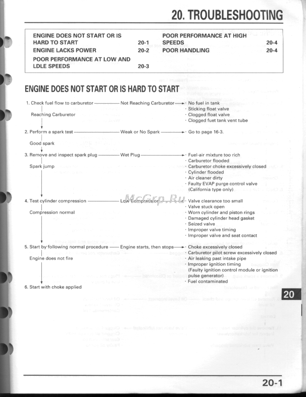 Honda CBR600F3Инструкция 21
 -
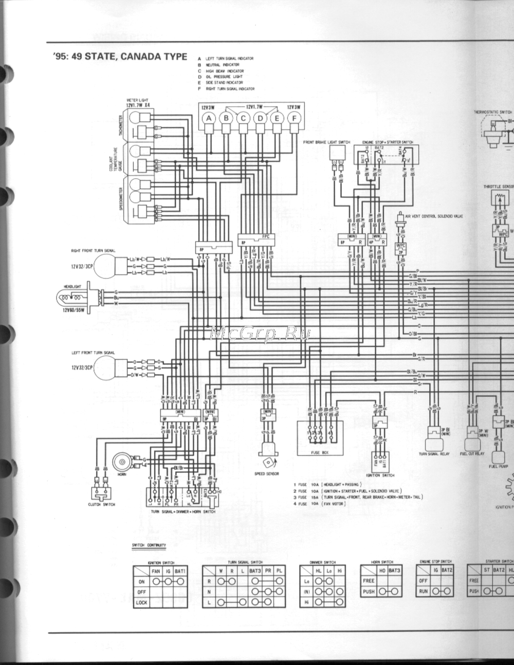 Honda CBR600F3Инструкция 20
 -
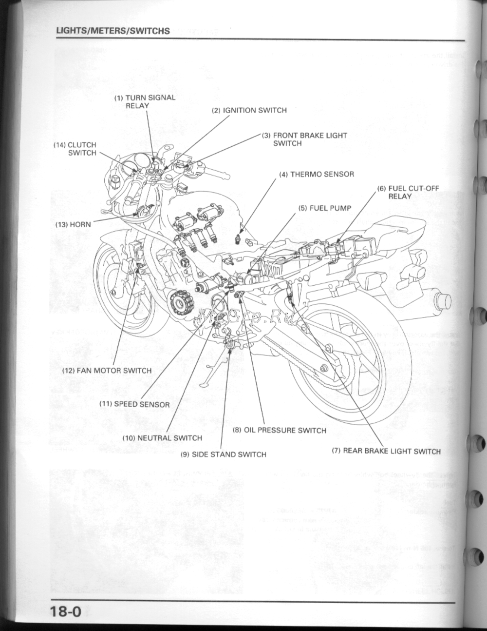 Honda CBR600F3Инструкция 19
 -
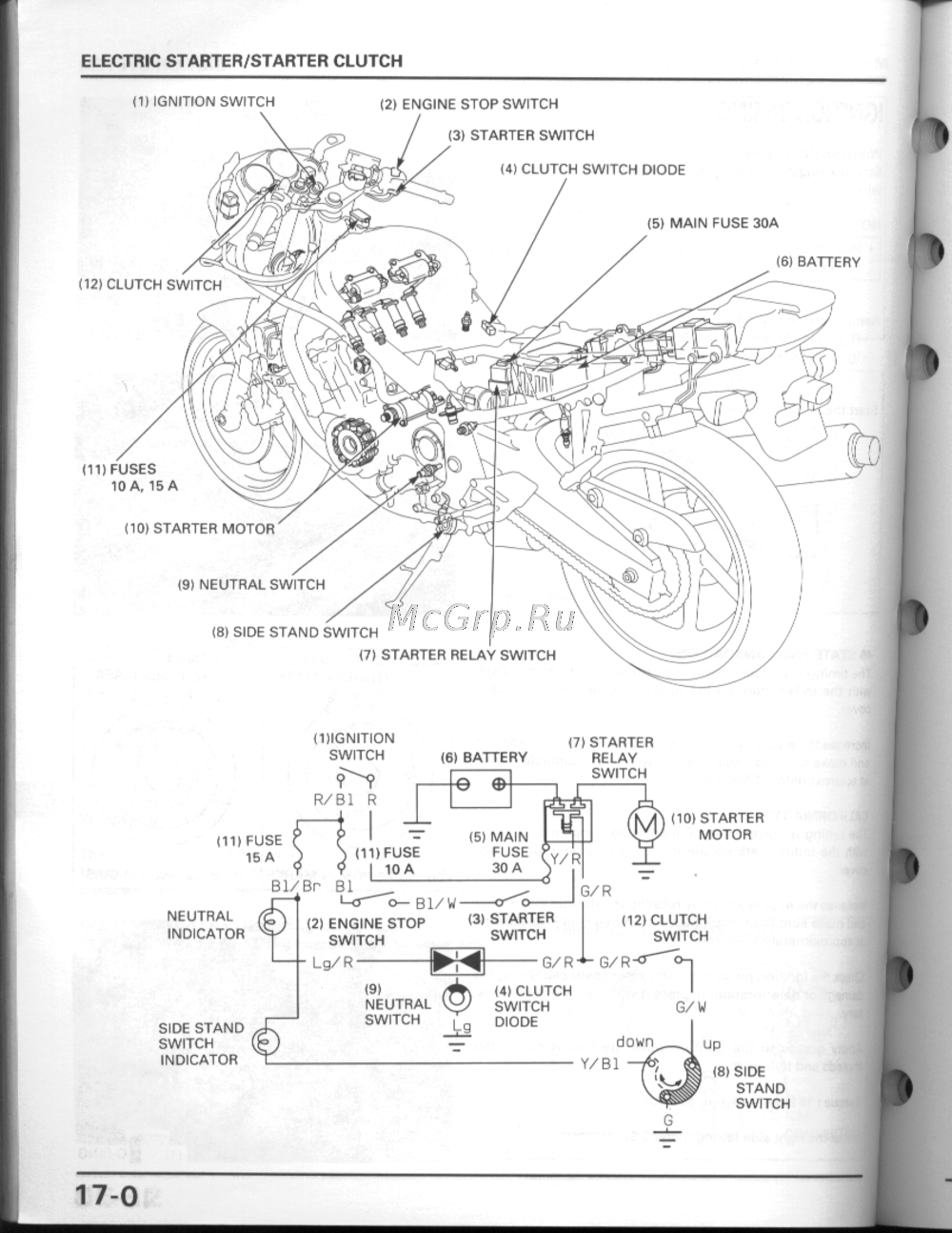 Honda CBR600F3Инструкция 18
 -
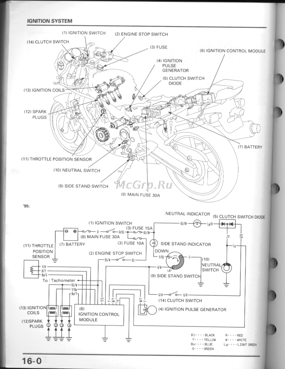 Honda CBR600F3Инструкция 17
 -
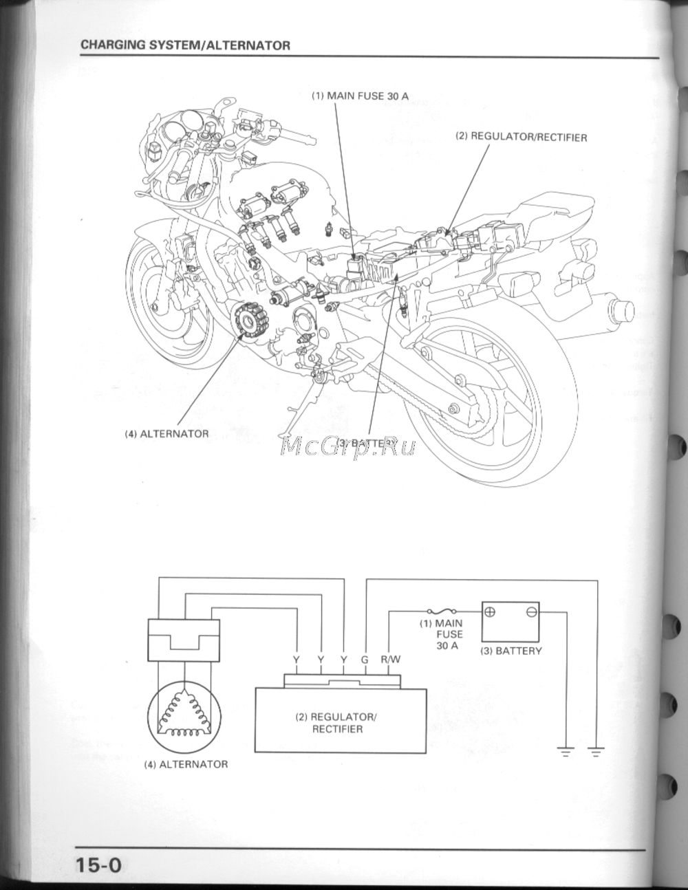 Honda CBR600F3Инструкция 16
 -
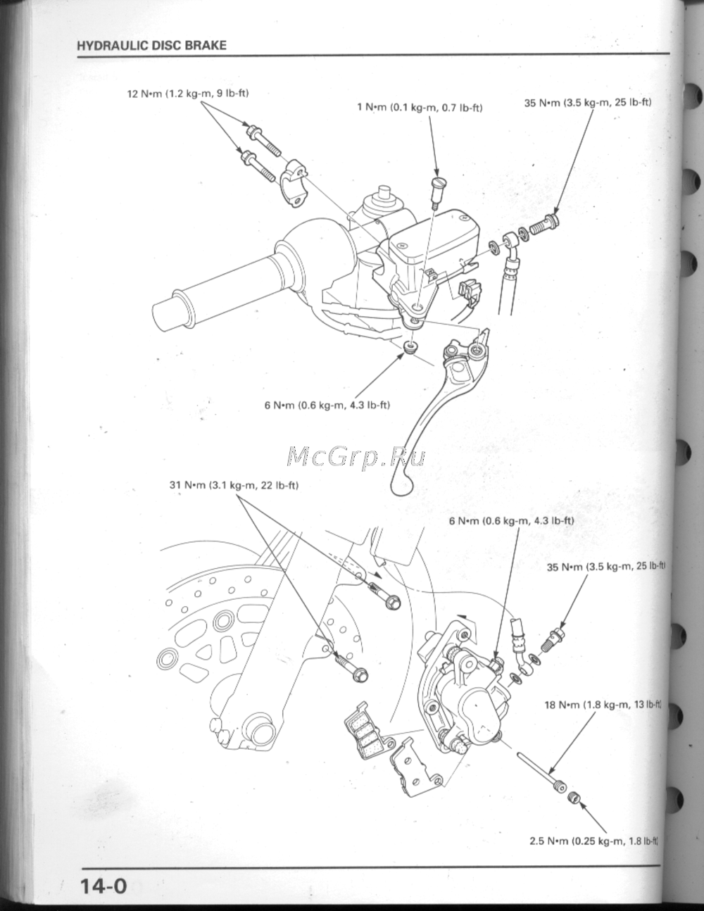 Honda CBR600F3Инструкция 15
 -
 Honda CBR600F3Инструкция 14
 -
 Honda CBR600F3Инструкция 13
 -
 Honda CBR600F3Инструкция 12
 -
 Honda CBR600F3Инструкция 11
 -
 Honda CBR600F3Инструкция 10
Узнайте о разнообразных аспектах и темах, которые могут вас заинтересовать. Мы предлагаем полезные советы и информацию для вашего удобства.