![GRAPHITE 59G800 — руководство по эксплуатации и настройке торцовочной пилы [13/108]](/img/pdf.png)
GRAPHITE 59G800 — руководство по эксплуатации и настройке торцовочной пилы [13/108]
Превью страниц
Страница 13 /
108
![GRAPHITE 59G800 [13/108] Preparation for operation](/views2/1382046/page13/bgd.png)
13
9. Cutting depth gauge
10. Cutting depth gauge adjustment screw
11. Guide locking knob
12. Guide
13. Head locking lever
14. Fence
15. Fixing hole
16. Angular scale of work table
17. Work table angle marker
18. Lever for automated position fixing
19. Work table locking knob
20. Table insert
21. Work table
22. Laser module cover
23. Laser unit
24. Fixed shield
25. Dust extraction outlet
26. Dust bag
27. Vertical clamp fixing knob
28. Vertical clamp arm
29. Vertical clamp arm locking knob
30. Work piece fixing knob
31. Angular scale of head tilt
32. Marker of head tilt position
33. Battery compartment
34. Laser switch button
35. Laser
36. Laser module fixing screws
37. Central plate fixing screw
38. Central plate
39. Adjustment knob for angle 0
0
40. Adjustment knob for angle 45
0
* Differences may appear between the product and drawing
MEANING OF SYMBOLS
CAUTION
WARNING
ASSEMBLY / SETTINGS
INFORMATION
EQUIPMENT AND ACCESSORIES
1. Dust bag - 1 pce
2. Special key - 1 pce
3. Vertical clamp - 1 pce
PREPARATION FOR OPERATION
Ensure the mitre saw is disconnected from power supply before
starting any installation or adjustment.
CARRYING THE MITRE SAW
• Make sure the head is locked in the lowest position when carrying
the mitre saw.
• Make sure that work table locking knob, head locking lever, and
other safety parts are tightened firmly.
INSTALLATION OF MITRE SAW ON A WORKBENCH
It is recommended to fix the mitre saw to a workbench or a stand
with the use of fixing holes (15) designed for such purpose. They
are located on the mitre saw base and guarantee safe operation
and eliminate risk of unwanted machine shifts during operation.
The holes allow to use coach bolts or bolts with hexagonal head and
8 mm in diameter.
When fixing the mitre saw to a workbench ensure that:
• Workbench top surface is flat and clean.
• Bolts are tightened equally and with moderate force (fixing bolts
must be tightened so the base is not under stress or deformed). In
case of over-stress there is danger of cracking the base.
DUST EXTRACTION
To prevent dust deposition and provide maximum working
efficiency, you can connect the mitre saw and industrial vacuum
cleaner using the dust extraction outlet (25). Alternatively, you can
collect the dust in the dust-bag (included) after installing it onto
dust extraction outlet. To install, press on the spring clamp and
put the dust bag (26) onto the dust extraction outlet (25) (g. A).
To empty the dust bag, press on the spring clamp of the dust bag,
remove it from the dust extraction outlet and open the zip-fastener
that allows to access inside the bag.
To achieve optimal dust extraction empty the bag when it is 2/3
full.
USING THE SAW ARM (HEAD)
There are two positions of the saw arm, upper and lower. To release
the saw arm from locked lower position, do as follows:
• Press and hold down the arm.
• Pull the head locking pin (8) out.
• Hold the saw arm as it lifts to its upper position.
To lock the saw arm in lower position, do as follows:
• Press and hold the cutting blade guard lever (4).
• Press down the saw arm until it reaches its lower position.
• Lock the extension arm in this position by pressing the head
locking pin (8) in.
VERTICAL CLAMP
Vertical pressure clamp (g. B) can be installed in the saw base at
either side of the work table and is fully adjustable to size of the
object to be cut. Do not use the saw without using vertical pressure
clamp.
• Loosen the vertical clamp fixing knob (27) at the base, on the side
where you plan to install the vertical clamp.
• To install the vertical clamp, slide it into the hole in the mitre saw
base, next tighten the vertical clamp fixing knob (27) to the saw
base.
• Once the vertical clamp arm (28) position is adjusted to work
piece, tighten the vertical clamp arm locking knob (29).
• Tighten the work piece fixing knob (30) so the work piece is
pressed against the work table (21).
• Make sure the work piece is secured.
OPERATION / SETTINGS
Ensure the saw is disconnected from power supply network before
starting any adjustment. To ensure safe, precise and ecient saw
operation, proceed with all adjustment procedures as a whole.
After nishing all the setting and adjustment procedures ensure
that all keys are collected. Check that all threaded joining
elements are properly tightened.
When making adjustments ensure that all external parts work
properly and are in good condition. Any worn out or damaged
part must be replaced by qualied personnel before starting to
use the saw.
SWITCHING ON / SWITCHING OFF
The mains voltage must match the voltage on the rating plate
of the saw.
Switch on the saw only when cutting blade is away from the
material that is to be cut.
Switching on
• Press and hold the switch button (3).
Switching o
• Release pressure on the switch button (3).
USING THE CUTTING DEPTH GAUGE
Cutting depth gauge is used for making key grooves in a work
Содержание
143- Instrukcja oryginalna obsługi pilarka ukosowa
- Szczegółowe przepisy bezpieczeństwa
- Przygotowanie do pracy
- Praca ustawienia
- Obsługa i konserwacja
- Parametry techniczne
- Ochrona środowiska ce
- Deklaracja zgodności we ec declaration of conformity megfelelési nyilatkozat ek
- Gwarancja i serwis
- Translation of the original instructions mitre saw
- Detailed safety regulations
- Preparation for operation
- Operation settings
- Operation and maintenance
- Übersetzung der originalbetriebsanleitung gehrungssäge
- Technical parameters
- Environment protection
- Detaillierte sicherheitsvorschriften
- Vorbereitung auf den einsatz
- Betrieb einstellungen
- Bedienung und wartung
- Перевод оригинальной инструкции торцовочная пила
- Umweltschutz ce
- Technische parameter
- Правила техники безопасности
- Подготовка к работе
- Работа настройка
- Обслуживание и консервация
- Технические характеристики
- Защита окружающей среды
- Спеціальні правила техніки безпеки
- Під час користування устаткуванням
- Переклад інструкції з оригіналу пилка торцовочна 59g800
- Підготовка до роботи
- Порядок роботи робочі налаштування
- Технічні характеристики
- Зберігання та обслуговування
- Охорона середовища се
- Részletes biztonsági előírások
- Eredeti használati utasítás fordítása gérfűrész 59g800
- A munka előkészítése
- Munkavégzés beállítások
- Műszaki jellemzők
- Kezelése és karbantartása
- Traducere a instrucţiunilor originale ferăstrau circular diagonal 59g800
- Reguli speciale de securitate
- Környezetvédelem ce
- Pregătirea pentru activitate
- Lucrul ajustarea
- Parametrii tehnici
- Deservire si intretinere
- Překlad původního návodu k používání pokosová pila
- Protecţia mediului ce
- Podrobné bezpečnostní pokyny
- Příprava k práci
- Provoz nastavení
- Péče a údržba
- Technické parametry
- Preklad pôvodného návodu na použitie pokosová píla
- Ochrana životního prostředí ce
- Detailné bezpečnostné predpisy
- Práca nastavenia
- Pred uvedením do prevádzky
- Ošetrovanie a údržba
- Technické parametre
- Specifični varnostni predpisi
- Prevod izvirnih navodil zajeralna žaga
- Ochrana životného prostredia ce
- Uporaba nastavitve
- Priprava na uporabo
- Vzdrževanje in hramba
- Tehnični parametri
- Varovanje okolja ce
- Originalios instrukcijos vertimas traukiamasis skersavimo pjūklas
- Detalios darbo saugos taisyklės
- Pasiruošimas darbui
- Darbas ir reguliavimas
- Techniniai duomenys
- Aptarnavimas ir priežiūra
- Instrukciju tulkojums no oriģinālvalodas leņķzāģis
- Detalizētie drošības noteikumi
- Aplinkos apsauga ir ce
- Sagatavošanās darbam
- Darbs iestatījumi
- Apkalpošana un apkope
- Tehniskie parametri
- Eriohutusjuhised
- Algupärase kasutusjuhendi tõlge nurgasaag
- Vides aizsardzība ce
- Töö seadistamine
- Ettevalmistus tööks
- Tehnilised parameetrid
- Kasutamine ja hooldus
- Превод на оригиналната инструкция циркулярен трион
- Подробни правила за безопасност
- Keskkonnakaitse ce
- Работа настройки
- Подготовка за работа
- Технически параметри
- Обслужване и поддръжка
- Опазване на околната среда ce
- Prijevod originalnih uputa nagibna pila
- Posebni propisi o sigurnosti
- Priprema za rad
- Rad postavke
- Rukovanje i održavanje
- Zaštita okoliša ce
- Tehnički parametri
- Prevod orginalnog uputstva kružna testera
- Opšti saveti za bezbednost
- Rad postavke
- Pripremaza rad
- Rukovanje i održavanje
- Μεταφραση του πρωτοτυπου των οδηγιων χρησησ φαλτσοπριονο
- Κανονεσ ασφαλειασ
- Zaštita sredine ce
- Tehničke karakteristike
- Προετοιμασια για εργασια
- Λειτουργια ρυθμιση
- Συντηρηση και φυλαξη
- Τεχνικα χαρακτηριστικα
- Προστασια περιβαλλοντοσ
- Traducción del manual original ingletadora 59g800
- Normas de seguridad detalladas
- Preparación para trabajar
- Trabajo ajustes
- Uso y mantenimiento
- Parametros técnicos
- Traduzione delle istruzioni originali troncatrice radiale
- Protección medioambiental ce
- Norme particolari di sicurezza
- Preparazione al funzionamento
- Funzionamento regolazioni
- Servizio e manutenzione
- Caratteristiche tecniche
- Gedetailleerde veiligheidsvoorschriften
- Vertaling van de originele handleiding van de verstekzaag
- Protezione dell ambiente ce
- Werkvoorbereiding
- Werk instellingen
- Technische parameters
- Bediening en onderhoud
- Milieubescherming ce
Похожие устройства
-
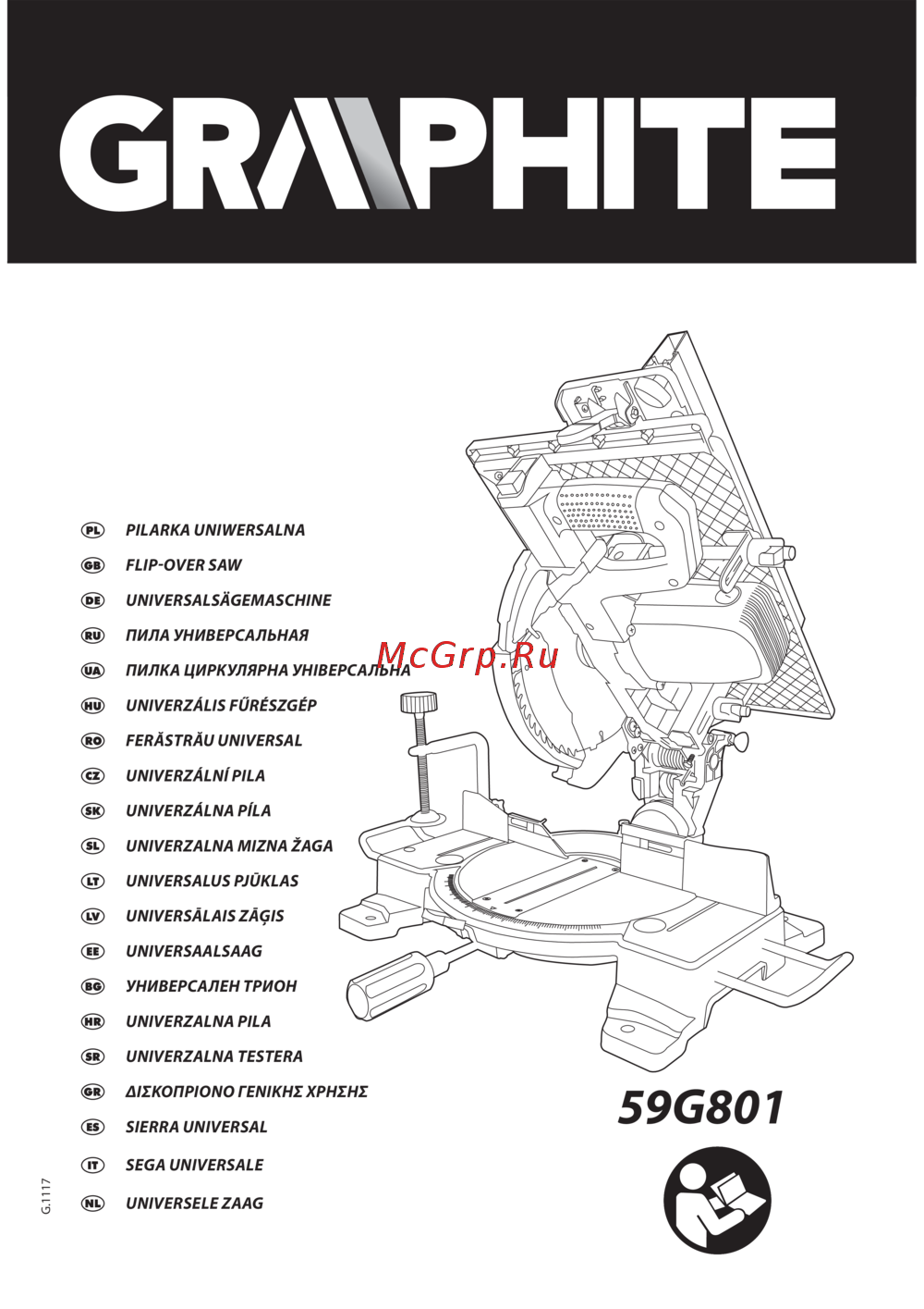 GRAPHITE 59G801Инструкция по эксплуатации
 -
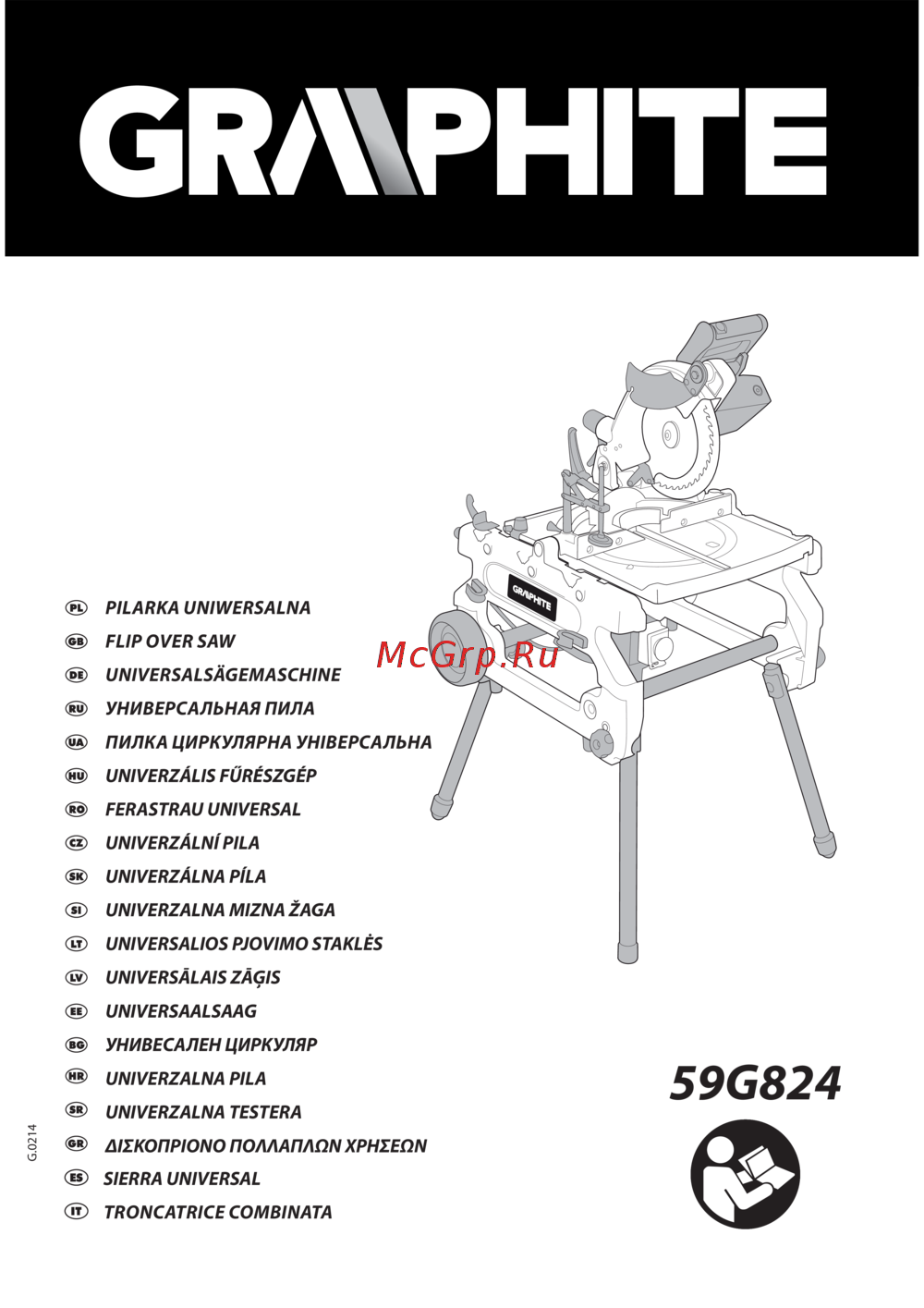 GRAPHITE 59G824Инструкция по эксплуатации
 -
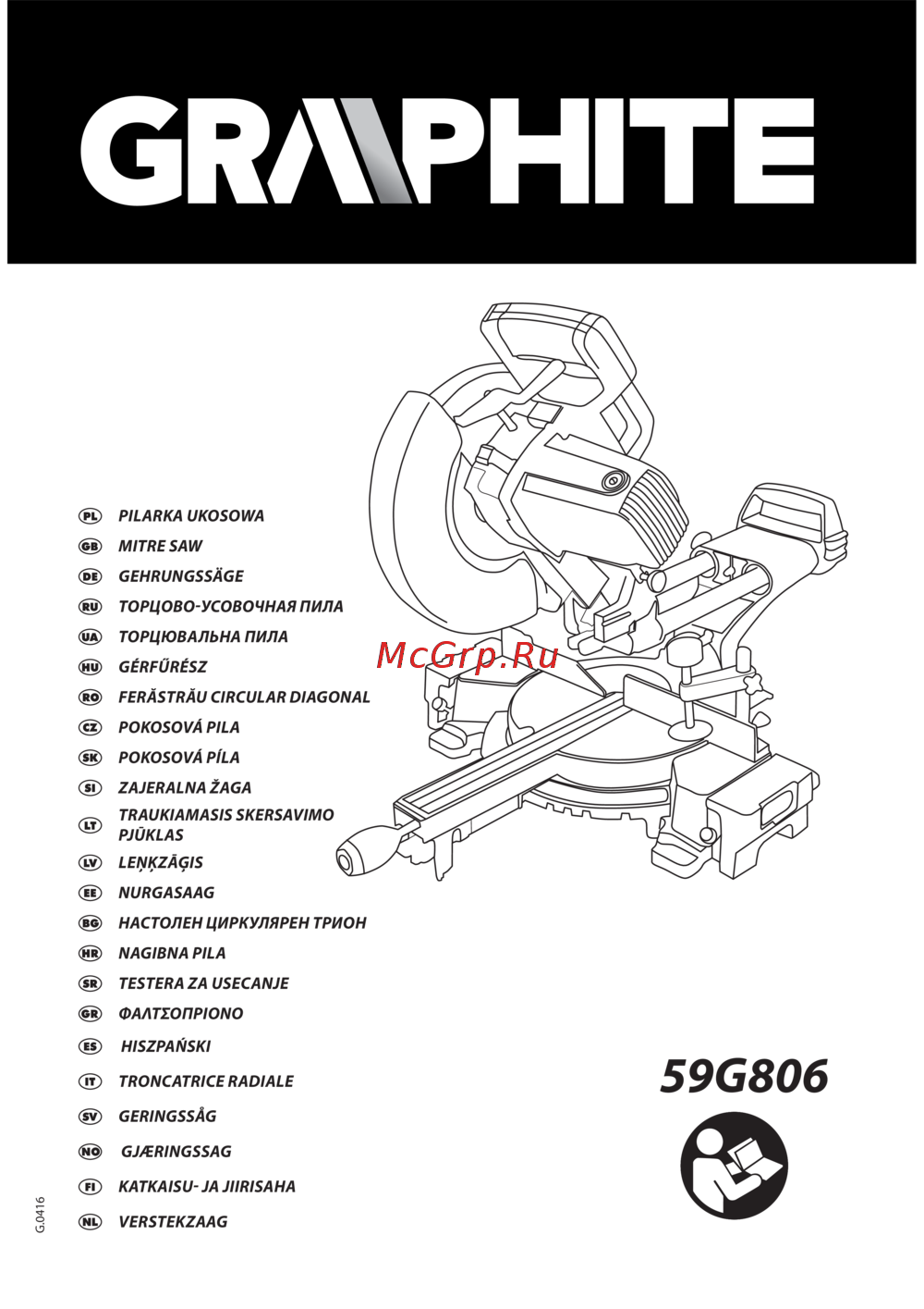 GRAPHITE 59G806Инструкция по эксплуатации
 -
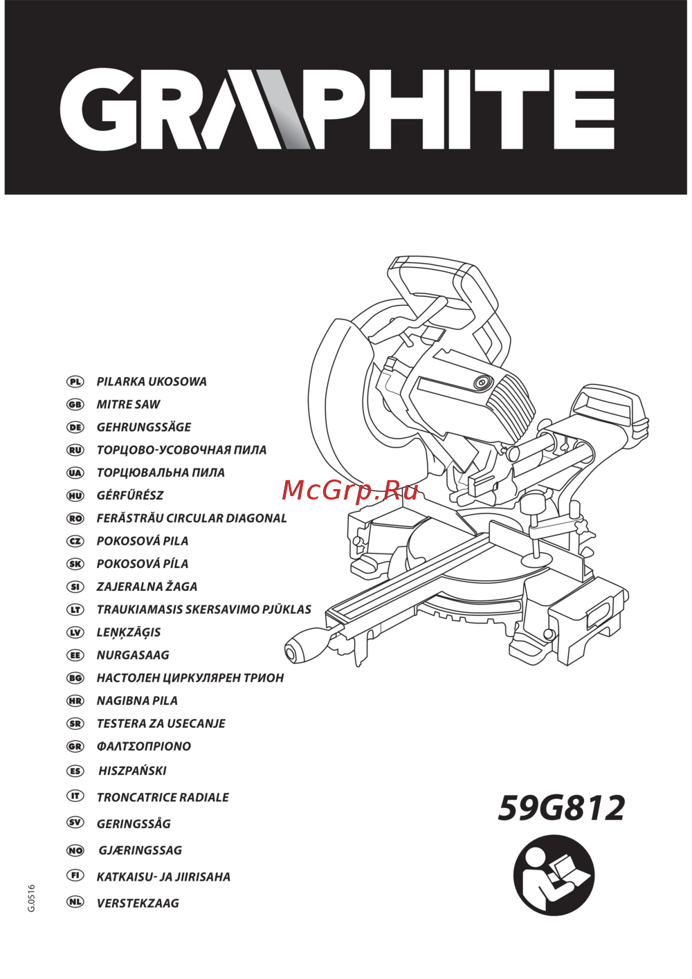 GRAPHITE 59G812Инструкция по эксплуатации
 -
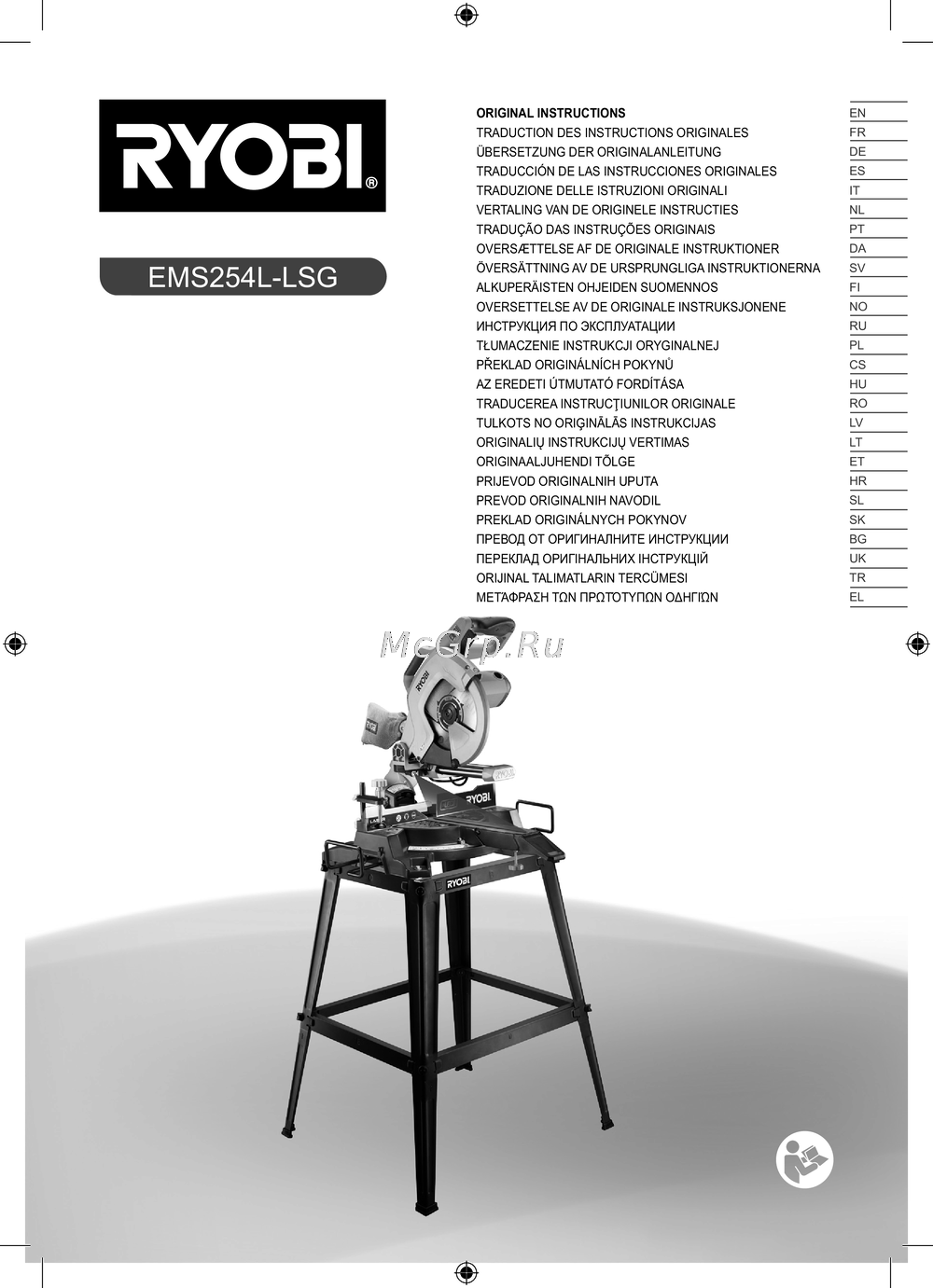 Ryobi EMS254L-LSGИнструкция к устройству
 -
 Elitech пт 1825кРуководство по эксплуатации
 -
 Hammer stl1200/210cИнструкция по эксплуатации
 -
Hammer STL1800/250CИнструкция по эксплуатации
-
 Hammer STL1800/255PИнструкция по эксплуатации
 -
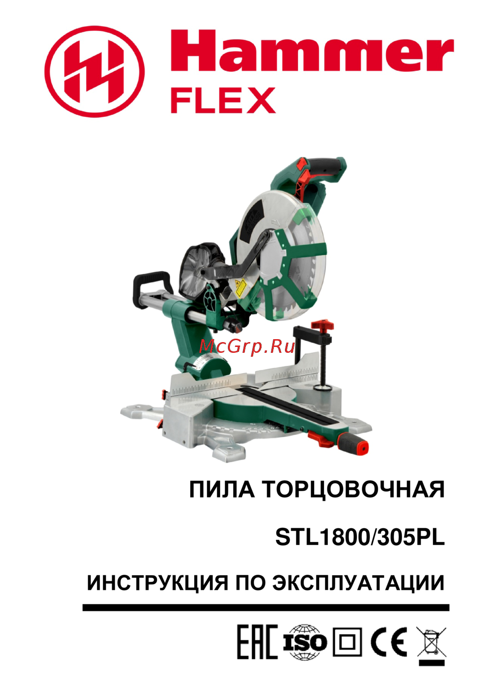 Hammer STL1800/305PLИнструкция по эксплуатации
 -
 Hammer stl800Инструкция по эксплуатации
 -
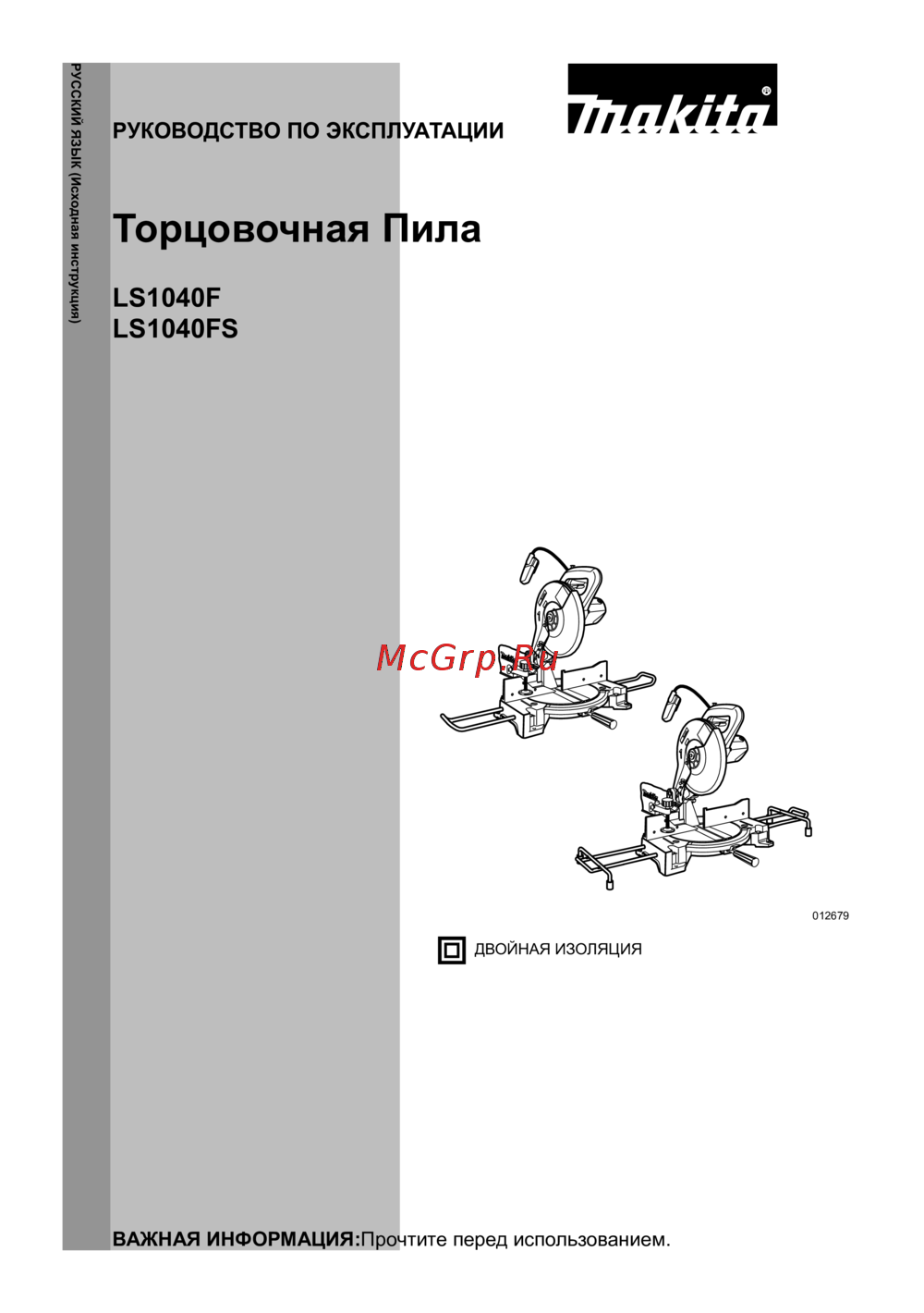 Makita LS1040FNИнструкция
Узнайте, как правильно установить и использовать торцовочную пилу. Подробные инструкции по настройке, безопасности и эффективному удалению пыли.