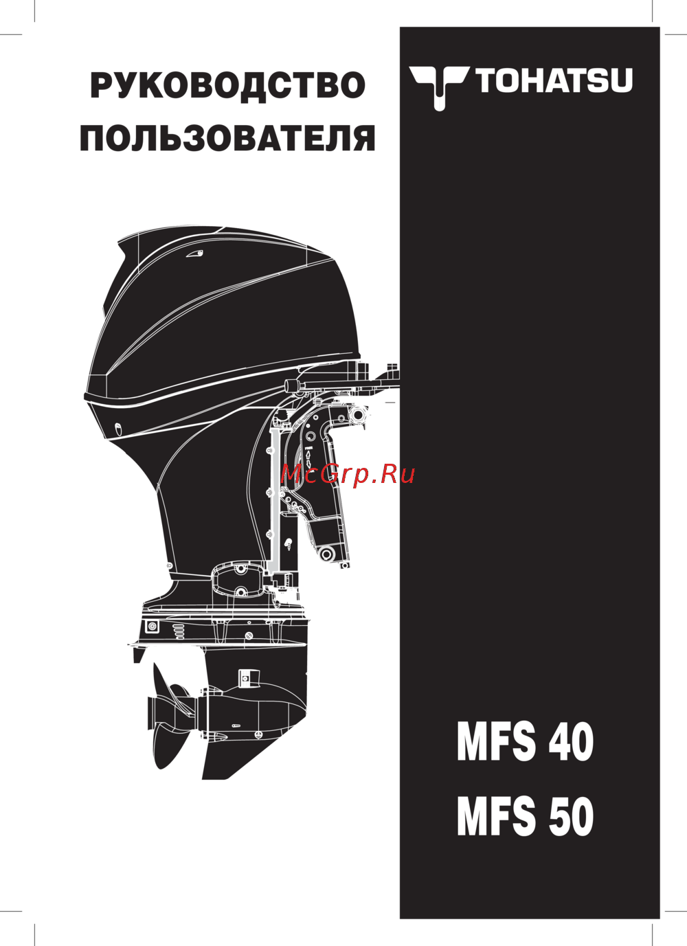
Tohatsu MFS 30 [314/319] Wiring diagram
Превью страниц
Страница 314 /
319
![Tohatsu MFS 30 [314/319] Wiring diagram](/views2/1240939/page314/bg13a.png)
11-2
Wiring Diagram
25/30 2006
NO. Name Remarks ECU Lead Wire Color ECU
1 Flywheel Magneto – – – –
2 Exciter Coils Located in the alternator A24 W/L White/Blue W/B
White/Black
A23
A2 W/R White/Red – –
3 ECU Charge Coil Located in the alternator A18 W White W White A19
4 Charge Coil Located in the alternator Å| Y Yellow Y Yellow –
5 Pulser Coil #1 A32 R/W Red/White B Black A15
6 Pulser Coils #2 A33 R/Y
Red/Yellow
B Black Earth
7 Rectifier
Optional on the recoil starting model
–YYellow R Red Battery
8 Fuse Holder
Optional on the recoil starting model
Battery R Red R Red Battery
9 MAT Sensor MAT A14 G/W
Green/White
B/L Black/Blue A34
0 Water Temperature Sensor WTS A8 G/Y
Green/Yellow
B/L Black/Blue A34
q Throttle Position Sensor TPS A7 L/W
Blue/White
R/L Red/Blue A17
w MAP Sensor MAP A13 G/L
Green/Blue
R/L Red/Blue A17
e Warning Lamp LED A10 Lg
Yellowish Green
W/R White/Red A1
r Oil Pressure Switch A5 Br/W
Brown/White
Earth –
t Stop Watch A3 Br Brown B Black A28
y Fuel Feed Pump FFP A22 L/B Blue/Black L Blue A1
u Fuel Injector #1 A29 Lg/R
Yellowish Green/Red
L Blue A1
i Fuel Injector #2 A30 Lg/B
Yellowish Green/Black
L Blue A1
o Fuel Injector #3 A31 Lg/L
Yellowish Green/Blue
L Blue A1
p ISC Valve Idle Speed Control Valve A16 G/R Green/Red L Blue A1
a Ignition Coil #1 A25 B/W
Black/White
B Black Earth
s Ignition Coil #2 A26 B/Y
Black/Yellow
B Black Earth
d Ignition Coil #3 A27 B/G
Black/Green
B Black Earth
f Spark Plugs #1 to #3 – High Tension Cable Earth –
g ECU Electronic Control Unit – – – –
h ECU Connector Main Harness – – –
j Service Connector Diagnosis Port – – – –
k Personal Computer Diagnosis – 9 Pin Serial Port RS232C –
l Battery
This battery can also be used as the one of v
Battery R Red B Black A28
; Cylinder Block Earth – Earth – –
z Bottom Cowl Earth – Earth – –
x Tachometer with Warning Lamp A12 W White Y Yellow –
Warning Lamp Located in the tachometer A9 Lg
Yellowish Green
R Red A1
c Warning Buzzer A11 Y Yellow R Red –
v Battery Battery R Red B Black A28
b Starter Motor Starter B Black B Black Starter
n Starter Solenoid Starter G Green R Red Battery
m PTT Motor – L Blue G Green –
, PTT Solenoid UP side – Sb Sky Blue L Blue –
. PTT Solenoid DOWN side – P Pink G Green –
/ PTT Switch Bottom Cowl – Sb Sky Blue P Pink –
! Start Switch Tiller Handle Model Starter G Green R Red Battery
@ Neutral Switch Tiller Handle Model Starter G Green G Green Starter
# Main Switch Key Remote Control Model Ignition R Red G Green Starter
$ Stop Watch Remote Control Model A3 Br Brown B Black Earth
% Warning Buzzer Remote Control Model A11 Y Yellow R Red Starter
^ Neutral Switch Remote Control Model Starter G Green R Red Starter
& PTT Switch Remote Control Model – Sb Sky Blue P Pink –
* Volt Meter Option Ignition R Red B Black Earth
( Fuel Meter Option – W White B Black –
) Hour Meter Option Ignition R Red B Black Earth
Q Speedometer Option – – – –
W Water Pressure Meter Option – – – –
E Trim Meter Option – P Pink Or Orange –
R Fuel Tank Sensor Option – R Red B Black –
T Meter Lamp Switch Option – L Blue R Red Ignition
Y Trim Sensor Option – P Pink Or Orange –
MFS25_30_ch11.qxd 06.3.9 5:05 PM ページ 2
Содержание
784- Ob no 03 21054 1 06 02 nb 2600
- Before reading this manual
- Information for securing of safety
- Introduction
- Mfs25_30_ch00 qxd 06 0 2 33 pm ページ 2
- B 1373b 1373b
- Description of pictogram
- The following symbols represent the contents of individual chapters
- The following symbols indicate items needed for the service
- The following symbols indicate a point to which lubrication oil sealing agent or screw locking agent is to be applied
- Fuel injection syste
- Fuel system fuel injection
- Ecu syste
- Cooling water system diagram
- Break in operation
- Maintenance data
- Parts layou
- Tightening torque data
- Test run
- Specifications
- Outline dimension
- Inspection items
- Special too
- Service information
- Checks after test run
- Maintenance
- Tools and instrument
- Inspection schedule
- Special tool
- Service data
- Securing of work safet
- Sealant application locations
- Pre delivery inspectio
- Piping arrangement diagra
- Ignition syste
- Special tool
- Parts layou
- Outline of fuel injection syste
- Inspection items
- Inspection item
- Power unit
- Lower unit
- Electrical system
- Ptt wiring and layout diagra
- Electrical component layou
- Starting syste
- Special tools
- Special tool
- Parts layou
- Inspection items
- Fuel control syste
- Bracket
- Wiring diagram
- Wiring chart
- Remote control component
- Ptt uni
- Ep epg ept model
- Ef efg eft model
- Accessories
- 3ac diagnosis
- Troubleshooting lis
- Troubleshooting
- Power uni
- Operation
- Mf mfg model
- Ecu couple
- Battery charging syste
- Test ru
- Break in operatio
- Tools and instrument
- Service information
- Securing of work safet
- Pre delivery inspectio
- Checks after test ru
- Ventilation
- Service information
- Securing of work safety
- Protection
- Identification engine serial number
- Genuine parts
- Fire prevention
- Recommendations on service
- Service information
- Cautions in disassembling and assembling components
- Tools and instruments
- Test propeller
- Measuring instruments
- Service information
- List of special tool
- Service information
- Pre delivery inspection
- Engine oil
- Steering handle
- Service information
- Gear shift
- Gear oil
- Rigging
- Inspection of ptt unit
- Inspection of gas shock absorber
- Fuel line
- Caution
- Service information
- Inspection of starting switch and stop switch
- Idling
- Propeller selection
- Propeller marking no of blades x diameter in mm x pitch in mm
- Cooling water check port
- Caution
- Trim tab
- Service information
- Break in operation
- Checks after test run
- Test run
- Service information
- Maintenance dat
- Fuel injection syste
- Tightening torque dat
- Specification
- Service data
- Outline dimension
- L size
- Engine dimensions
- Service data
- Outline dimensions
- Transom bolts
- Ptt or gas assisted model
- Mechanical tilt model
- Center line
- Service data
- Fuel injection system
- Ecu fuel feed system
- Engine lubrication system diagram
- Cooling water system diagram
- Service data
- Specifications
- Service data
- Service data
- Maintenance data
- Engine parts
- Functional limit action to be taken
- Engine parts fuel and lubrication parts
- Service data
- Functional limit action to be taken
- Electrical parts
- Service data
- Part name item standard value
- Functional limit action to be taken
- Cooling system parts
- Service data
- Part name item standard value
- Lower unit parts other parts ptt parts
- Functional limit action to be taken
- Tightening torque data
- Service data
- Standard tightening
- Service data
- Sealant application locations
- Service data
- Special too
- Maintenance
- Inspection schedule
- Inspection items
- Special tool
- Maintenance
- Inspection schedule
- Maintenance
- Inspection of top cowl
- Inspection of fuel system piping
- Inspection items
- Inspection of fuel tank
- Inspection of fuel filter
- Replacement of engine oil
- Maintenance
- Replacement of oil filter
- Maintenance
- Inspection of water pump
- Inspection of gear oil quantity
- Replacement of gear oil
- Maintenance
- Inspection of gear case for leakage
- Maintenance
- Inspection of timing belt
- Replacement of timing belt
- Caution
- Maintenance
- Caution
- Installation of timing belt
- Caution
- Caution
- Maintenance
- Inspection of spark plugs
- Inspection of compression pressure
- Maintenance
- Caution
- Inspection and adjustment of valve clearance
- Mark a
- Throttle cable adjustment of throttle link
- Maintenance
- Warning
- Maintenance
- Inspection of shift lever gear operations
- Warning
- Maintenance
- Inspection of ptt unit operation
- Inspection of gas assistant unit operations
- Warning
- Maintenance
- Inspection of ptt fluid quantity
- Inspection of ignition timing
- Inspection of idle speed
- Inspection of anodes
- Caution
- Replacement of anodes
- Maintenance
- Inspection of thermostat
- Inspection of propeller
- Maintenance
- Inspection of cooling water passage
- Caution
- Warning
- Flushing with water
- Maintenance
- Warning
- Lower a
- Inspection of battery
- Maintenance
- Greasing points
- Ecu system
- Special tool
- Piping arrangement diagra
- Parts layou
- Inspection item
- Ignition syste
- Fuel system fuel injection
- Special tools
- Fuel system fuel injection
- Starboard side
- Rear section port side
- Piping arrangement diagram
- Fuel hose vent hose breather hose cooling water hose
- Parts layout
- P l fig 5
- Fuel system fuel injection
- Fuel pump fuel rail vapor separator
- St oil
- P l fig 5
- N m 4 lb ft 0 kgf m
- Fuel pump fuel rail vapor separator
- St oil
- P l fig 5
- Fuel system fuel injection
- Fuel pump fuel rail vapor separator
- St oil
- P l fig 4
- Intake manifold
- P l fig 8
- N m 4 lb ft 0 kgf m
- Magneto ecu
- Fuel system fuel injection
- Electric parts
- P l fig 9
- Fuel system fuel injection
- P l fig 9
- Electric parts
- Separate fuel tank
- P l fig 24
- Fuel system fuel injection
- Ecu system
- 1 configuration of ecu system
- Sensors
- Fuel system fuel injection
- Actuators
- Fuel system fuel injection
- Control system ecu
- 2 control system
- 3 fuel injection control
- Injection timing diagram
- Fuel injection timing
- Starting fuel increase correction
- Fuel system fuel injection
- Deceleration fuel decrease correction
- Correction based on intake air temperature
- Correction based on cylinder cooling water temperature
- Acceleration fuel increase correction
- 5 control of tachometer
- 4 control of fuel feed pump ffp
- Locations of warning buzzer and lamp led
- Warning notification abnormality and action to be taken
- Warning buzzer and lamp led and control of engine revolution speed
- Ignition system
- Fuel system fuel injection
- 1 configuration of ignition system
- Operations
- Ignition timing controls
- Ignition timing
- Ignition and combustion orders
- 2 ignition control
- Fuel system fuel injection
- Fuel air
- 3 fuel feed system
- Vapor separator
- Fuel pump low pressure mechanical pump
- Components of fuel feed system
- Fuel system fuel injection
- Fuel regulator
- Fuel cooler
- Outline of fuel injection system
- Air intake system
- Inspection of filter
- Inspection items
- Fuel system fuel injection
- Inspection of fuel pump
- Inspection of fuel connector
- Fuel system fuel injection
- Warning
- Measuring fuel pressure
- Warning
- Inspection of fuel regulator
- Fuel system fuel injection
- Warning
- Draining fuel
- Disassembly of vapor separator
- Inspection of vapor separator
- Fuel system fuel injection
- Reassembly of vapor separator
- Inspection of isc idle speed control
- Inspection of idle speed
- Special tool
- Power unit
- Parts layou
- Inspection items
- Special tools
- Power unit
- Parts layout
- Engine
- Recoil starter
- Power unit
- P l fig 11
- N m 4 lb ft 0 kgf m
- Magneto ecu
- P l fig 8
- Power unit
- P l fig 9
- Electric parts
- P l fig 9
- Electric parts
- St oil
- Power unit
- P l fig 5
- N m 4 lb ft 0 kgf m
- Fuel pump fuel rail vapor separator
- St oil
- P l fig 5
- N m 4 lb ft 0 kgf m
- Fuel pump fuel rail vapor separator
- Fuel pump fuel rail vapor separator
- St oil
- Power unit
- P l fig 5
- St oil
- P l fig 4
- Intake manifold
- St oil
- Power unit
- P l fig 6
- Cam shaft oil pump
- Cylinder head
- St oil
- P l fig 1
- St oil
- Power unit
- Intake valve exhaust valve p l fig 7
- St oil
- P l fig 2
- Cylinder
- St oil
- Power unit
- Piston crankshaft
- P l fig 3
- Top cowl
- P l fig 23
- Power unit
- Inspection of compression pressure
- Inspection items
- Inspection of oil pressure
- Mark b
- Inspection of valve clearance
- I a ii d
- Power unit
- Removing power unit
- Power unit
- Caution
- Power unit
- Caution
- Removing timing belt and pulley
- Caution
- Power unit
- Inspection of timing belt
- Installation of pulley and timing belt
- Caution
- 4 5 6 7
- Power unit
- Caution
- Power unit
- Removing cylinder head
- Caution
- Power unit
- Inspection of valve spring
- Inspection of valve guide
- Inspection of valve
- Power unit
- Inspection of valve seat
- Correction of valve seat
- Power unit
- Inspection of rocker arm and rocker arm shaft
- Caution
- Power unit
- Inspection of cam shaft
- Inspection of cylinder head
- Inspection of oil pump
- Power unit
- Installation of valves
- Power unit
- Installation of rocker arm shaft
- Installation of cam shaft
- Installation of oil pump
- Power unit
- Installation of cylinder head
- Disassembly of cylinder block
- Power unit
- Inspection of piston outer diameter
- Inspection of piston clearance
- Inspection of cylinder inner diameter
- Inspection of piston rings
- Inspection of piston ring side clearance
- Inspection of connecting rod big end side clearance
- Power unit
- Inspection of piston pins
- Inspection of connecting rod small end inner diameter
- Inspection of crankshaft
- A a a a
- Power unit
- Inspection of crank pin oil clearance
- Inspection of crank shaft main journal oil clearance
- Thickness of bearing color of inner diameter code
- Power unit
- Inner diameter of cylinder crank case
- I ii iii iv
- Bearing holder inner diameter code
- A a a a
- Assembling piston and connecting rod
- Power unit
- Power unit
- Installation of power unit
- Power unit
- Caution
- Removing recoil starter
- Disassembly of recoil starter
- Power unit
- Inspection of recoil starter
- Installation of recoil starter
- Power unit
- Special tool
- Parts layout
- Lower unit
- Inspection items
- Special tools
- Lower unit
- Parts layout
- P l fig 14
- Lower unit
- Gear case
- P l fig 15
- N m 4 lb ft 0 kgf m
- N m 18 lb ft 2 kgf m
- Drive system water pump
- A projection b hole
- P l fig 15
- N m 4 lb ft 0 kgf m
- N m 18 lb ft 2 kgf m
- Lower unit
- Drive system water pump
- A projection b hole
- P l fig 16
- Removing propeller
- Lower unit
- Inspection items
- Draining gear oil
- Removing lower unit
- Disassembly of water pump
- Removing propeller shaft housing ass y
- Lower unit
- Inspection of water pump
- Inspection of propeller shaft
- Disassembly of propeller shaft ass y
- Caution
- Assembly of propeller shaft ass y
- Lower unit
- Disassembly of propeller shaft housing
- Inspection of propeller shaft housing
- Lower unit
- Assembly of propeller shaft housing
- Removing pump case lower
- Removing clutch cam and cam rod
- Disassembly of pump case lower
- Disassembly of clutch cam and cam rod
- Assembly of pump case lower
- Removing drive shaft
- Lower unit
- Inspection of cam rod and clutch cam
- Disassembly of drive shaft
- Assembly of cam rod and clutch cam
- Inspection of pinion gear b gear and forward gear a gear
- Inspection of drive shaft
- Disassembly of forward gear a gear
- Assembly of forward gear a gear
- Assembly of drive shaft
- Lower unit
- Disassembly of gear case
- Caution
- Inspection of gear case
- Assembly of lower unit
- Lower unit
- Installation of pinion gear b gear
- B7 72731 0
- 72733 0
- 72732 0
- Settling pinion gear b gear height
- Lower unit
- Settling forward gear a gear backlash
- Lower unit
- Lower unit
- Reassembly of pinion gear nut b gear nut
- Assembly of propeller shaft housing
- Reassembly of pump case lower
- Lower unit
- Assembly of water pump
- Lower unit
- Installation of lower unit
- Warning
- Lower unit
- Special tools
- Ptt wiring and layout diagra
- Parts layou
- Inspection items
- Bracket
- Mount puller kit p n 361 72760 0
- Bracket
- Special tools
- Removing upper mount
- Ptt wiring and layout diagram
- Parts layout
- P l fig 13
- Drive shaft housing
- Bracket
- Swivel bracket mechanical tilt
- P l fig 19
- P l fig 18
- N m 8 lb ft 1 kgf m
- Clamp bracket reverse lock
- Bracket
- 6 34 33
- 5 2 8 9
- Bracket ptt gas assistant
- P l fig 20
- N m 8 lb ft 1 kgf m
- N m 17 lb ft 2 kgf m
- N m 8 lb ft 1 kgf m
- N m 17 lb ft 2 kgf m
- Bracket ptt gas assistant p l fig 20
- Bracket
- Power trim tilt
- P l fig 21
- N m 5 lb ft 0 kgf m
- N m 4 lb ft 0 kgf m
- N m 18 lb ft 3 kgf m
- N m 112 lb ft 15 kgf m
- N m 1 lb ft 0 kgf m
- A chamfer
- 25 8 7
- Tiller handle
- P l fig 12
- Bracket
- P l fig 22
- Bottom cowl
- P l fig 16
- Bracket
- P l fig 17
- N m 30 lb ft 4 kgf m
- Installation of tiller handle
- Inspection of throttle cable
- Inspection items
- Bracket
- Adjustment of co pilot plate
- Removing drive shaft housing
- Bracket
- Pulling out upper mount
- Disassembly of drive shaft housing
- Inspection of oil strainer
- Bracket
- Assembly of drive shaft housing
- Installation of drive shaft housing ass y
- Removing steering shaft
- Installing steering shaft
- Bracket
- Removing clamp bracket ptt or gas assistant model
- Removing clamp bracket mechanical tilt model
- Bracket
- Installation of clamp bracket ptt or gas assistant model
- Installation of clamp bracket mechanical tilt model
- Removing ptt unit gas shock absorber
- Bracket
- Removing ptt pump and valves
- Removing ptt motor
- Inspection of ptt pump and valves
- Caution
- Removing tilt cylinder
- Inspection of tilt cylinder
- Caution
- Bracket
- Installation of ptt pump and motor
- Inspection of valve
- Bracket
- Assembly of tilt cylinder
- Warning
- Bracket
- Air purging ptt unit separated from outboard motor
- Bracket
- Installation of ptt unit gas shock absorber
- Warning
- Air purging ptt unit installed on the outboard motor
- Up down
- Inspection of ptt solenoid
- Bracket
- Inspection of ptt switch
- Starting syste
- Special tools
- Parts layout
- Fuel control system
- Electrical system
- Electrical component layout
- Ecu coupler
- Battery charging system
- Electrical system
- Special tools
- Electrical component layout port side view
- Electrical system
- Bow side view
- Starboard side view
- Top view
- Electrical system
- Tiller handle model
- Parts layout
- P l fig 8
- Magneto ecu
- Electrical system
- P l fig 9
- Electric parts
- Electrical system
- Electric parts
- P l fig 9
- Starter motor
- P l fig 10
- 13 1 7
- St oil
- P l fig 5
- N m 4 lb ft 0 kgf m
- Fuel pump fuel rail vapor separator
- Electrical system
- St oil
- P l fig 5
- N m 4 lb ft 0 kgf m
- Fuel pump fuel rail vapor separator
- Inspection of ignition sparks
- Ignition system ignition control system
- Electrical system
- Inspection of plug cap
- Inspection of ignition coils
- Inspection of alternator
- Inspection of pulser coil
- Inspection of oil pressure switch
- Electrical system
- Off on
- Inspection of water temperature sensor
- Inspection of start switch tiller handle model
- Inspection of neutral switch tiller handle model
- Inspection of stop switch
- Electrical system
- Inspection of isc valve
- Inspection of injectors
- Fuel control system
- Electrical system
- Inspection of throttle position sensor
- Inspection of mat manifold temperature sensor
- Inspection of fuel feed pump ffp
- Starting system
- Inspection of starter solenoid
- Inspection of fuse
- Disassembly of starter motor
- Inspection of starter motor pinion
- Inspection of armature
- Electrical system
- 3 3 3 3 3 1
- Inspection of starter motor operation
- Inspection of brushes
- Inspection of alternator
- Electrical system
- Battery charging system
- Inspection of rectifier
- Ecu coupler
- Electrical system
- Troubleshooting list
- Troubleshooting
- Starting system
- Power unit
- Troubleshooting
- Yes yes
- Warning
- Ignition system
- Troubleshooting
- Fuel system
- Troubleshooting
- State 2
- Ignition system
- Troubleshooting
- Yes yes
- Fuel system
- Troubleshooting
- Lubrication system
- Cooling system
- Troubleshooting
- Ignition system
- Warning
- Troubleshooting
- Fuel system
- State 1 ptt will not operate
- Ptt unit
- Troubleshooting
- Caution
- Ac diagnosis
- Warning
- Set up
- Troubleshooting
- Software install
- If putting cd into cd drive will not cause installation software to start
- Diagnosis file information
- Troubleshooting
- Hardware connection
- Position of on off switch for function test and running drop test
- Troubleshooting
- Operating procedure
- Setting communication com port rs232c port
- Troubleshooting
- Monitoring ecu data
- Monitoring history and failure code retrieval
- Function test
- Troubleshooting
- Running test drop test
- Troubleshooting
- Explanation of error code
- Exit diagnostic
- Troubleshooting
- Accessories
- Accessories
- Remote control model
- Remote control components
- Warning
- Caution
- Accessories
- Installation of meters and battery
- Installation of meters
- Installation of battery
- Wiring diagram of remote and control meters
- Accessories
- Operation
- Warning indication
- Accessories
- Wiring diagram
- Wiring char
- Mf mfg mode
- Ep epg ept mode
- Ef efg eft model
- Wiring diagram
- Ob no 03 21054 1 06 02 nb 2600
Похожие устройства
-
 Tohatsu MFS 40Инструкция по эксплуатации
 -
 Tohatsu MFS 30Каталог запчастей
 -
 Tohatsu MFS 30Инструкция по эксплуатации
 -
 Tohatsu MFS 30Схема электропроводки
 -
 Tohatsu MFS 25Сервис Мануал
 -
Tohatsu MFS 25Каталог запчастей
-
Tohatsu MFS 25Схема электропроводки
-
Tohatsu MFS 25Инструкция по эксплуатации
-
 Tohatsu MFS 20Каталог запчастей
 -
Tohatsu MFS 20Схема электропроводки
-
 Tohatsu MFS 20Инструкция по эксплуатации
 -
Tohatsu MFS 15Каталог запчастей